
ultrasonic cleaning transducers series parallel

The ultrasonic cleaning device operates by converting electrical energy into high-frequency sound waves through the transducer(s). The existing design utilizes a single 50W transducer, which is capable of generating the necessary ultrasonic waves for effective cleaning. The proposed design modification involves the integration of two 20W transducers, which may enhance cleaning efficiency if configured correctly.
When considering the configuration of the transducers, the impedance matching is vital for optimal performance. In parallel, two 20W transducers would yield an equivalent impedance of 15 Ohms, which aligns more closely with the typical 20 Ohm impedance of a standard transducer. This configuration may provide better power distribution and efficiency, allowing for effective operation without overloading the power source.
Conversely, wiring the transducers in series would result in a combined impedance of 60 Ohms, which could lead to underperformance due to insufficient power delivery to each transducer. The series configuration may also require adjustments to the driving circuit to accommodate the higher impedance, potentially complicating the design.
In addition to impedance considerations, the physical placement of the transducers is crucial. Precise alignment is necessary to ensure that the ultrasonic waves produced do not interfere destructively, which could diminish the cleaning effectiveness. This requires careful measurement and adjustment during assembly.
Furthermore, safety precautions are paramount when working with circuits that involve mains voltage. Proper insulation, circuit breakers, and other protective measures should be implemented to prevent electric shock or equipment damage. Additionally, attention must be paid to components sensitive to electrostatic discharge, ensuring that they are handled in a controlled environment to prevent failure.
In summary, the choice of series or parallel configuration for the transducers should be guided by impedance matching principles, operational efficiency, and safety considerations. Adjustments to component values and circuit design may be necessary during the construction phase to achieve the desired performance of the ultrasonic cleaning device.A small ultrasonic cleaning device and it runs 1 x 50W transducer at the moment. I am going to build another that uses two 20W transducers and was just wondering what the best configuration is, to wire them in series or in parallel My circuit designs should be regarded as experimental. Although they work in simulation, their component values may need altering or additional components may be necessary when the circuits are built. Due safety precautions should be taken with any circuit involving mains voltage or electrostatic-sensitive components. You are going to have to position your transducers at very precise distances from each other to avoid them canceling one another out.
It depends on the impedance of the 20watt unit compared to the 50watt unit, you do need to impedance match, I`m thinking series is probably the way to go, With the Ohms at 30 per 20W parallel would make it 15 Ohms which is probably closer to the 20 Ohms of the standard transducer as opposed to series that would make it 60 Ohms 🔗 External reference
Related Circuits
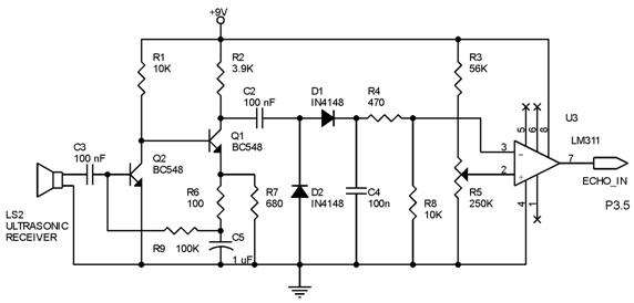
Techniques for an echo sounder used to measure ocean depth can be implemented with an ultrasonic distance measuring device. This device uses a circuit similar to the one described in the previous article, which includes a series of ultrasonic...
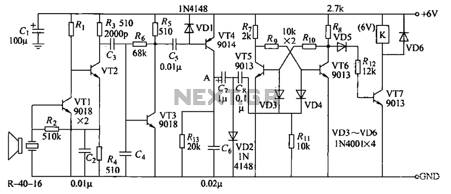
The circuit consists of transistors VT1 through VT7 and other components. Due to the weak signal received from the transmitter, the circuit employs a multi-stage amplifier to enhance the output. This output generates a square wave pulse signal to...
The file being accessed no longer exists. It may have been renamed or removed from the archive. Navigation links are available on the left to browse the desired area of the archive. The connection is to cdn.preterhuman.net, which mirrors...
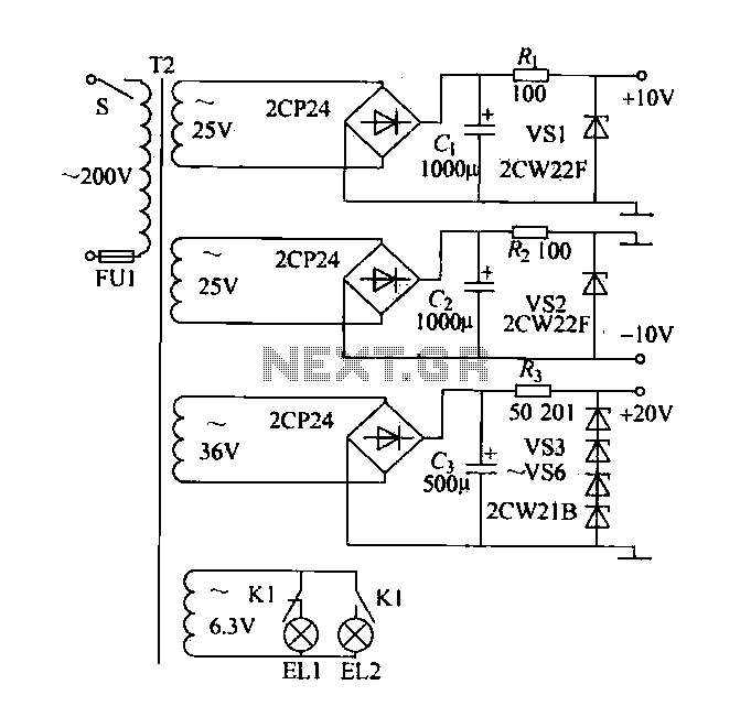
A DC power supply with a shunt, rectifier, filter, current limiting, and voltage regulation, providing 10V voltage outputs. The circuit is simple and low cost, designed to meet the requirements of various applications. Additionally, it features a 3V indicator...
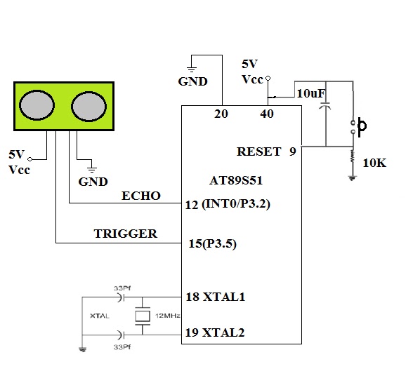
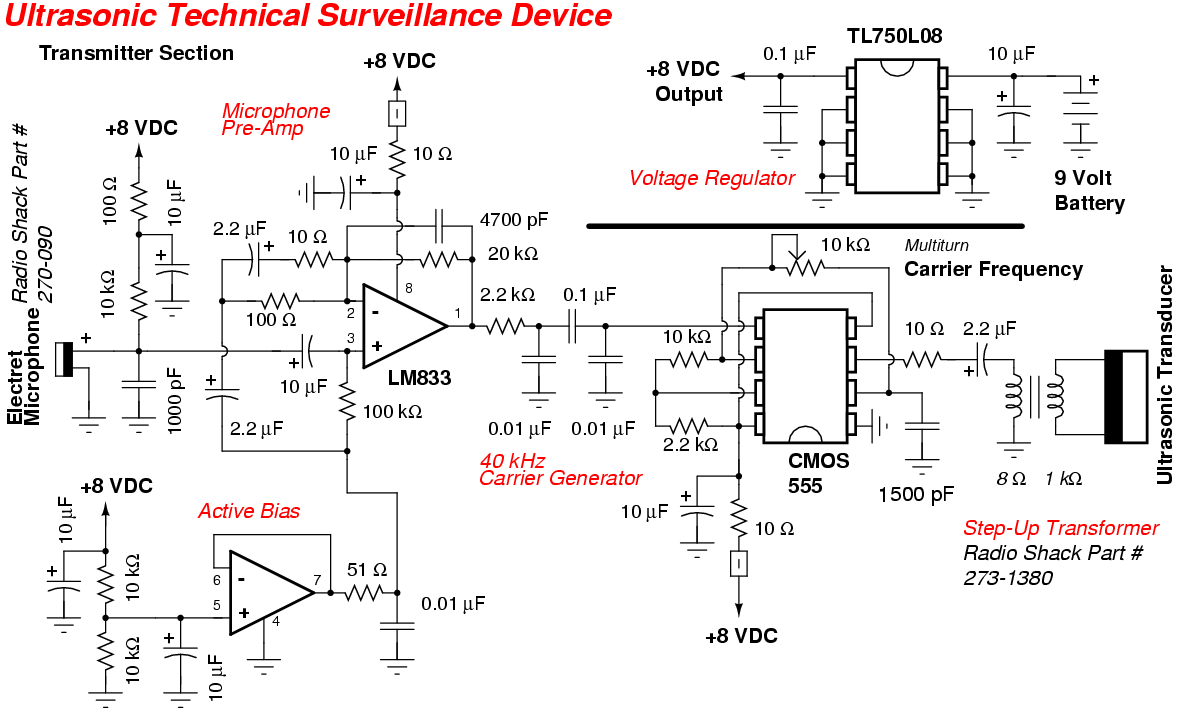
To enable a robot to detect objects in its surroundings, an ultrasonic sensor is recommended. While infrared (IR) sensors are inexpensive, their operational range can fluctuate due to ambient light changes, resulting in inaccurate range measurements. Ultrasonic sensors operate...
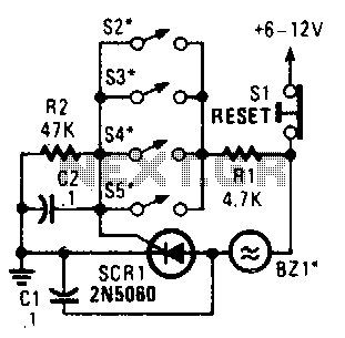
Four parallel switches are employed to monitor four positions. When any switch is closed, SCR1 is triggered, activating the alarm. The alarm is designed to be of the non-interrupting type. The circuit consists of four parallel switches, each representing a...