
ultrasonic sensor interfacing with 8051
The operation of an ultrasonic sensor involves several steps:
1. Set the "Trig" pin of the sensor high for 10 µs to initiate a sensor cycle.
2. The sensor's transmitting piezo transducer sends out 8 pulses at a frequency of 40 kHz, after which the "Echo" pin transitions from low to high.
3. The emitted 40 kHz sound wave reflects off the nearest object and returns to the sensor.
4. Upon detecting the reflected sound wave, the Echo pin returns to a low state.
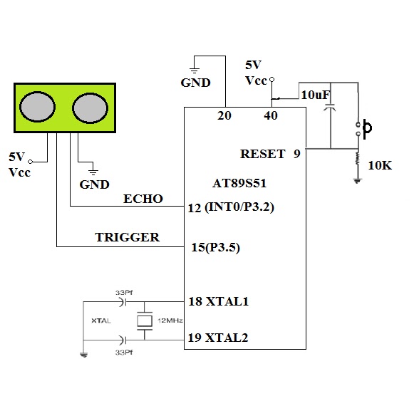
5. To interface the sensor with the AT89S51 microcontroller, two I/O pins are required: one for an external interrupt pin (INT0 or INT1) to measure the pulse width at the echo pin, and another pin, such as P3.5, for the trigger.
6. Configure TIMER0 of the 8051 microcontroller in 16-bit mode with the GATE bit enabled. When the GATE pin is enabled and the timer run control bit TR0 is set, TIMER0 will be controlled by the INT0 pin. TIMER0 starts counting when INT0 is high and holds its count when INT0 goes low. The TMOD register should be loaded with the value 00001010 (0x0A), as referenced in 8051 documentation.
The ultrasonic sensor's design and implementation in a robotic application involve careful consideration of the interfacing with the microcontroller, as well as the timing and pulse width measurement for accurate distance calculation. The use of TIMER0 allows for precise timing control, essential for effective distance measurement. By enabling the GATE function, the timer can be synchronized with the interrupt signals, ensuring that the timing of the echo pulse is accurately captured. This method of operation provides reliable object detection capabilities, making ultrasonic sensors a preferred choice for robotic applications requiring environmental awareness.If you want to make your robot sense the objects in it`s surroundings i suggest you to go for an ULTRASONIC sensor. Though the IR based sensors are cheep, their working range may vary due change in ambient light and won`t give accurate range values.
In case of ULTRASONIC sensors they work based on the principle of RADAR(RAdio Detection And Ranging). A RADAR transmits electromagnetic "pulse" towards the target and receives the "echo" reflected by the target. Then the range of the target is determined by the "time lagging" between transmitted pulse and the received "echo".
Generally microwave and ultrasonic frequencies are used in RADARS STEP1. Make "Trig" pin of the sensor high for 10 µs. This initiates a sensor cycle. STEP2. 8 x 40 kHz pulses will be sent from the transmitting piezzo transducer of the sensor, after which time the "Echo" pin on the sensor will go from low to high. STEP3. The 40 kHz sound wave will bounce off the nearest object and return to the sensor. STEP4. When the sensor detects the reflected sound wave, the Echo pin will go low again. STEP6. To inter face the sensor to AT89S51 microcontroller we need two I/O pins. One of them is external interrupt pin(INT0 or INT1) for measuring the pulse width at the echo pin. and any other pin say P3. 5 for trigger. STEP3. Configure the TIMER0 of 8051 in 16 bit mode with GATE bit enabled. If the GATE pin is enabled and timer run control bit TR0 is set, the TIMER0 will be controlled by INT0 pin.
When INT0 is high then the TIMER0 starts counting. Whenever INT0 goes low TIMER0 holds its count. So load the TMOD register with 00001010=0x0A; (better refer to any book of 8051). 🔗 External reference
Related Circuits
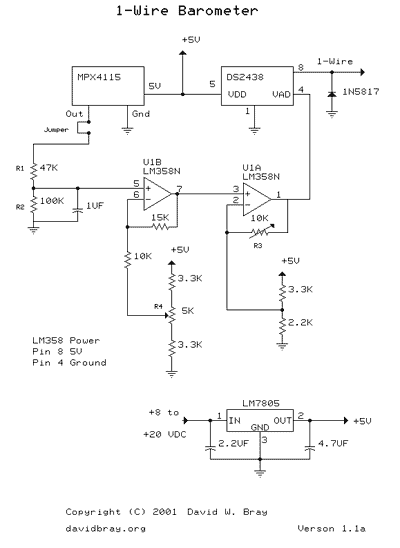
This design uses a Motorola MPX4115 Silicon Pressure Sensor, a Dallas Semiconductor DS2438 Smart Battery Monitor (to perform 1-Wire analog to digital conversion), an operational amplifier, a voltage regulator, a diode, and several resistors and capacitors. The circuit requires...
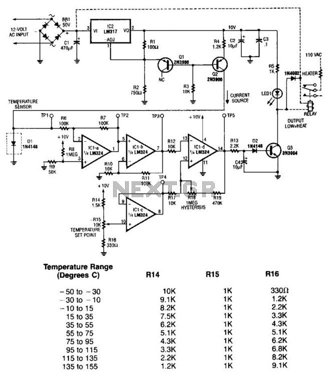
This simple circuit senses heat from electronic devices and provides a warning alarm. It is an ideal add-on circuit for monitoring heat in CD players, amplifiers, and similar equipment. The circuit utilizes a 14-stage ripple-free binary counter IC, the...
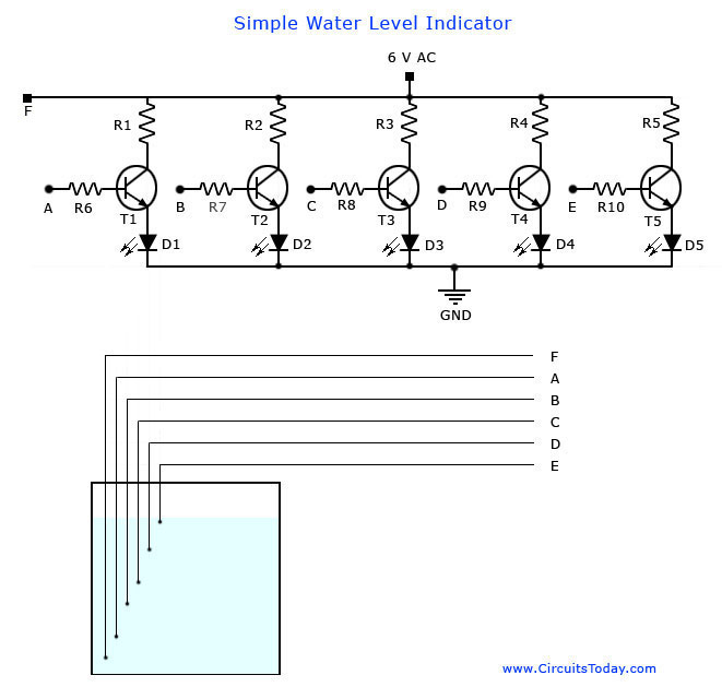
A simple water level indicator project with a circuit diagram for home and industry. This water tank level sensor can be utilized for any liquid level indicator projects. The water level indicator circuit is designed to monitor and display the...
Q1, Q2, and Q3 form a high-impedance super-Darlington configuration that drives the relay, amplifying the 50 or 60 Hz alternating mains supply frequency induced in the sensor by the human body. Capacitors C1, D2, and D3 ensure clean switching...
The LM35 temperature sensor outputs 10 mV/C for each degree Celsius above 0°C. At 20°C, the output voltage is calculated as 20 × 10 = 200 mV. The circuit consumes minimal power. Additionally, the load resistance should not be...
The Resistive Sensor Head (A2053) is a Long-Wire Data Acquisition (LWDAQ) device that measures the resistance of up to eleven resistive sensors. These sensors can include 1000-Ω RTDs (Resistance Temperature Devices), 100-Ω RTDs, 120-Ω strain gauges, or similar resistive...