
Ultrasonic Dog Whistle

The circuit design primarily revolves around the 555 timer, which is configured in astable mode to generate a square wave output. The frequency of oscillation is determined by the resistor-capacitor (RC) network formed by the potentiometer and capacitor. The piezo beeper is connected to the output of the 555 timer, converting the electrical signal into audible sound waves. The variable resistor allows for fine-tuning of the frequency to match the sensitivity range of different dogs.
In practical implementation, the circuit can be assembled on a perf board, ensuring that all connections are secure and that the components are properly oriented. The power supply can be connected directly to the circuit, with appropriate bypass capacitors placed across the power supply lines to stabilize operation and reduce noise.
For testing, a simple sound level meter or a smartphone application can be used to measure the output sound levels at various frequencies. This will help in determining the most effective frequency range for training purposes. Additionally, housing the circuit in a plastic enclosure not only protects the components but also allows for portability, making it easy to carry and use in different environments.
The addition of an LED pilot light serves as a visual indicator of the circuit's operation, enhancing user feedback. Overall, this design provides a versatile tool for dog training, leveraging the unique auditory capabilities of canines while remaining straightforward and cost-effective. Further enhancements could include integrating a microcontroller for programmable frequency patterns or additional features such as remote activation.It`s well known that many animals are particularly sensitive to high-frequency sounds that humans can`t hear. Many commercial pest repellers based on this principle are available, most of them operating in the range of 30 to 50 kHz.
My aim was, however, to design a slightly different and somewhat more powerful audio frequency/ultrasonic sound gene rator that could be used to train dogs. Just imagine the possibilities - you could make your pet think twice before barking again in the middle of the night or even subdue hostile dogs (and I guess burglars would love that!). From what I`ve read, dogs and other mammals of similar size behave much differently than insects. They tend to respond best to frequencies between 15 and 25 kHz and the older ones are less susceptible to higher tones.
This means that an ordinary pest repeller won`t work simply because dogs can`t hear it. Therefore, I decided to construct a new circuit (based on the venerable 555, of course) with a variable pitch and a relatively loud 82 dB miniature piezo beeper. The circuit is very simple and can be easily assembled in half an hour. Most of the components are not really critical, but you should keep in mind that other values will probably change the operating frequency.
Potentiometer determines the pitch: higher resistance means lower frequency. Since different dogs react to different frequencies, you`ll probably have to experiment a bit to get the most out of this tiny circuit. The circuit is shown below: Despite the simplicity of the circuit, there is one little thing. The 10nF (. 01) capacitor is critical as it, too, determines the frequency. Most ceramic caps are highly unstable and 20% tolerance is not unusual at all. Higher capacitance means lower frequency and vice-versa. For proper alignment and adjustment, an oscilloscope would be necessary. Since I don`t have one, I used Winscope. Although it`s limited to only 22 kHz, that`s just enough to see how this circuit works. There is no need to etch a PCB for this project, perf board will do. Test the circuit to see how it responds at different frequencies. A 4k7 potentiometer in conjunction with a 10nF (or slightly bigger) capacitor gives some 11 to 22kHz, which should do just fine.
Install the circuit in a small plastic box and if you want to, you can add a LED pilot light. Power consumption is very small and a 9V battery should last a long time. Possible further experimentation: I`m working on an amplified version of the whistle to get a louder beep. All attempts so far haven`t been successful as high frequency performance tends to drop dramatically with the 555.
Perhaps I could use a frequency doubler circuit - I just don`t know and I`ve run out of ideas. One other slightly more advanced project could be a simple "anti-bark" device with a sound-triggered (clap) switch that sets off the ultrasonic buzzer as soon as your dog starts to bark. 🔗 External reference
Related Circuits
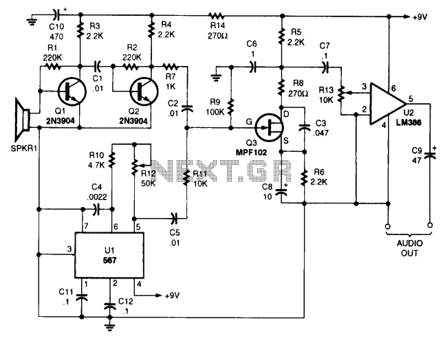
The performance of this sensitive ultrasonic receiver is impressive. It allows users to listen to various sources of ultrasonic sounds, including insects, bats, engines, and more. The circuit employs a piezo tweeter as an ultrasonic microphone, along with amplifier...
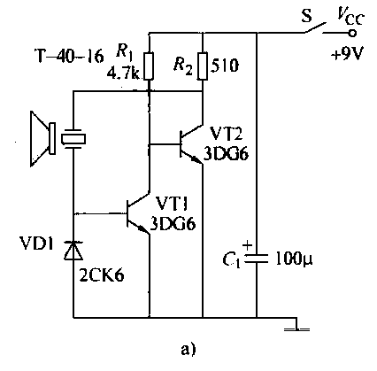
The T-40-16 and 555 ultrasonic transmitter circuit configuration consists of an ultrasonic transmitter T-40-16 and a 555 timer circuit. By adjusting the potentiometer RP, the oscillation frequency of the circuit can be changed. The output pulse frequency from the...
This device emits intermittent beeping for approximately two seconds when a whistle is detected within a range of several meters. The first two inverters in IC1 function as audio amplifiers. IC1A consistently amplifies the signal captured by a small...
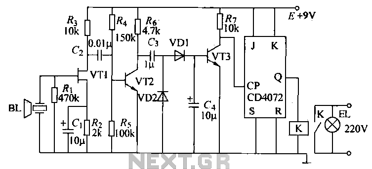
The ultrasonic transmitter circuit T-40-16, along with various discrete components, functions as a feedback sensor. The transistors VT1 and VT2 create a robust positive feedback oscillator that converts an electric signal into an ultrasonic oscillation signal, with the oscillation...
Many commercial pest repellers operate in the frequency range of 30 to 50 kHz. The goal was to design a more powerful audio frequency and ultrasonic sound generator suitable for training dogs. This device could potentially deter dogs from...
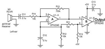
Assistance is required regarding the circuits provided below. The focus is on an ultrasonic receiver circuit that utilizes two ultrasonic components. The ultrasonic receiver circuit is designed to detect ultrasonic waves, typically in the frequency range of 20 kHz to...