
Ultrasonic Receiver Sircuit Diagram
The ultrasonic receiver circuit utilizes the CA3140 operational amplifier, known for its high input impedance and low noise characteristics, making it suitable for sensitive applications such as ultrasonic signal detection. The circuit typically incorporates a piezoelectric transducer that converts ultrasonic sound waves into electrical signals.
When ultrasonic waves strike the transducer, it generates a small voltage signal corresponding to the frequency of the incoming sound. This signal is then fed into the CA3140, which amplifies the voltage to a more usable level. The gain of the amplifier can be adjusted through external resistors, allowing for flexibility in sensitivity based on the application requirements.
The output of the CA3140 can be further processed or analyzed, often interfacing with microcontrollers or signal processing units for tasks such as distance measurement or object detection. Additional components such as filters may be included in the circuit to eliminate noise and improve the clarity of the received ultrasonic signals.
Overall, the CA3140-based ultrasonic receiver circuit serves as an essential tool in various applications, including robotics, automotive systems, and industrial automation, where precise distance sensing and object detection are critical.The following circuit shows about Ultrasonic Receiver Sircuit Diagram. Thicircuit based on the CA3140IC. Features: The frequency of sound produced .. 🔗 External reference
Related Circuits
This circuit detects motion within approximately 5 inches of a piezo-ceramic element ultrasonic transducer. The detection distance is much smaller than obtainable with other ultrasonic techniques; however, it only requires a single transducer, as opposed to the two-transducer arrangement...

The circuit is primarily composed of the integrated voice chip ISD2560. The Winbond ISD2560 is a chip with robust voice recording capabilities, featuring a permanent memory circuit for voice recording. It has a recording duration of 60 seconds and...
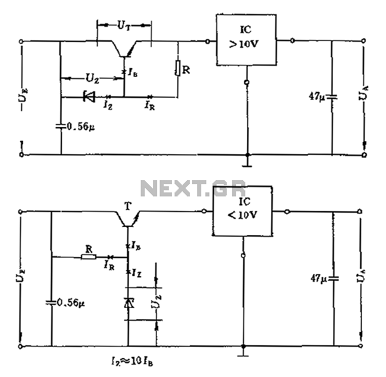
The voltage equation Ue = Ut + Ur + Ua indicates that the transistor voltage Ut will determine the maximum output voltage Ua. Additionally, Ur must be 2V. The voltage regulator's voltage value depends on the selection of Uz....
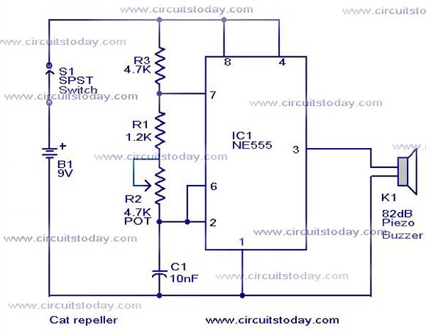
This cat and dog repeller circuit is designed to deter animals from specific areas. The circuit utilizes ultrasonic sound, which is known to provoke a strong response in many animals, particularly cats. The design features an astable multivibrator configuration...
This audio amplifier design utilizes two LM3886 chips per channel in a parallel configuration, based on the PA100 parallel amplifier detailed in National Semiconductor's application note AN1192. The amplifier can deliver approximately 50W into an 8-ohm speaker and 100W...
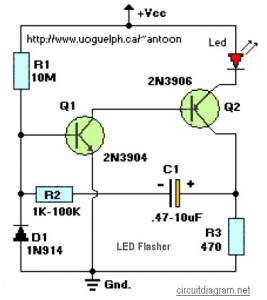
This circuit is designed to flash a high-brightness red LED (5000 mcd), making it suitable for use in fake car alarms or other devices intended to attract attention. The specific values of the components are not critical, allowing for...