
Capacitive Sensor
The circuit utilizes a super-Darlington transistor configuration formed by Q1, Q2, and Q3, which is designed to achieve high input impedance and significant current gain. This configuration is particularly effective for detecting low-level signals, such as those induced by the human body through capacitive coupling. The alternating current (AC) frequency of 50 or 60 Hz from the mains supply is amplified, allowing the relay to switch on in response to human presence.
Capacitor C1 serves as a coupling capacitor, blocking any direct current (DC) components and allowing only the AC signal to pass through to the base of the Darlington pair. Diodes D2 and D3 are used for flyback protection, ensuring that any back EMF generated by the relay coil during switching does not damage the transistor components. This arrangement results in a reliable and efficient relay operation.
The power supply requirement specifies the use of a commercial wall plug-in transformer adapter. This adapter should have an integrated rectifier and smoothing capacitor to convert the AC voltage to a stable DC voltage suitable for the relay operation. It is vital that the power supply can deliver adequate current to meet the relay's specifications.
For safety and proper circuit functionality, it is crucial that the circuit ground is connected through a small value, high voltage-rated capacitor to one side of the mains supply socket. This connection helps to isolate the circuit from the mains while allowing it to sense the AC signal. The "Live" side of the mains supply socket must be identified and connected correctly to ensure the circuit operates safely and effectively.Q1, Q2 & Q3 form a high impedance super-Darlington that drives the relay, amplifying the 50 or 60Hz alternate mains-supply frequency induced in the sensor by the human body. C1, D2 & D3 ensure a clean switching of the relay. Power supply can be any commercial wall plug-in transformer adapter with rectifier and smoothing capacitor, capable of suppl
ying the voltage and current necessary to power the relay you intend to use. * For proper operation, circuit ground must be connected via a small value, high voltage-rating capacitor to one side of the mains supply socket. The "Live" side is the right one. 🔗 External reference
Related Circuits
This schematic diagram illustrates a 555 IC water level sensor and detector alarm circuit. The circuit is powered by the emitter current of the BC109C transistor. The 555 timer operates as an astable oscillator in this configuration. Under dry...
This two-part article explains the utilization of a simple voltage divider circuit incorporating a thermistor to obtain high-accuracy temperature readings across a wide range of measurements. The first part focuses on the circuit design and explores various methods for...
This circuit illustrates a color sensor circuit diagram. The design is grounded in the principles of optics and digital electronics. The color sensor circuit typically employs a light-sensitive component, such as a photodiode or phototransistor, to detect and differentiate colors...
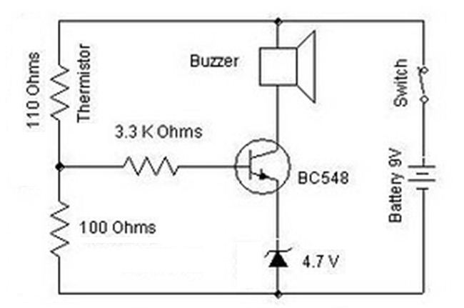
A heat sensor circuit can be utilized to control any device using a heat sensor. In this circuit, a thermistor and a resistor are connected in series, forming a potential divider circuit. The thermistor is of the Negative Temperature...
The Arduino microcontroller board can supply a current of 40mA from its output connections, with digital outputs fixed at 5V for "ON" and 0V for "OFF." This current is suitable for LEDs, but devices like motors, solenoids, and high-brightness...
Dew (condensed moisture) adversely affects the normal performance of sensitive electronic devices. A low-cost circuit described here can be used to switch off any gadget automatically in case of excessive humidity. At the heart of the circuit is an...