HEAT SENSOR image

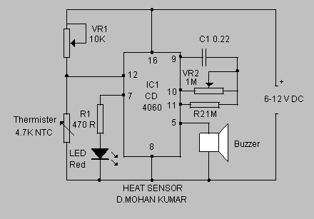
This simple circuit senses heat from electronic devices and provides a warning alarm. It is an ideal add-on circuit for monitoring heat in CD players, amplifiers, and similar equipment. The circuit utilizes a 14-stage ripple-free binary counter IC, the CD4060. This IC features an internal oscillator, with its frequency determined by components C1, VR2, and R2. The operation of the IC is controlled by reset pin 12. When pin 2 is high, the IC remains off, and it activates when pin 12 goes low. A variable resistor, in conjunction with an NTC thermistor, forms a potential divider that sets the voltage level at pin 12. Under normal temperature conditions, the resistance of the thermistor is high, keeping IC1 off. Once the temperature exceeds the threshold set by VR1, IC1 begins oscillating, causing a red LED to blink. After a few seconds, a buzzer sounds, indicating that the temperature within the device is rising. This allows the user to switch off the device immediately to prevent damage. The circuit should be enclosed within the device, with the thermistor positioned close to the heat-generating area. Power for the circuit can be sourced from the device itself.
This heat-sensing circuit is designed to provide a reliable warning system for electronic devices that may be prone to overheating. The CD4060 IC serves as the core of the circuit, featuring a built-in oscillator that generates a frequency used to monitor temperature levels. The frequency is adjusted through the capacitor C1, variable resistor VR2, and resistor R2, allowing for fine-tuning based on specific requirements.
The NTC thermistor plays a crucial role in temperature detection. As temperature increases, the resistance of the thermistor decreases, which alters the voltage at pin 12 of the CD4060. This change in voltage is critical for the operation of the circuit; when the voltage drops below a certain threshold, the IC is activated, initiating the alarm sequence.
The blinking red LED serves as a visual indicator of the alarm status, providing immediate feedback to the user that the device is experiencing elevated temperatures. The subsequent activation of the buzzer after a set delay adds an auditory warning, further alerting the user to the potential risk of overheating.
For optimal performance, it is essential to place the thermistor in proximity to components that generate significant heat. This ensures that the circuit responds promptly to any temperature changes. Additionally, the power supply for the circuit can be conveniently drawn from the electronic device it is monitoring, simplifying installation and reducing the need for external power sources.
Overall, this circuit provides an effective solution for monitoring temperatures in sensitive electronic devices, helping to prevent damage due to overheating and enhancing the longevity and reliability of the equipment.This simple circuit senses heat from electronic devices and gives warning alarm. It is an ideal add on circuit to monitor heat in CD players, Amplifiers etc. The circuit uses 14 stage ripple free binary counter IC CD 4060. It has an internal oscillator and its frequency is set by C1, VR2 and R2. Reset pin 12 of IC determines its working. When pin1 2 is high, IC remains off and turns on when pin 12 becomes low. Variable resistor along with the NTC Thermister forms a potential divider to set the voltage level at pin12. When the temperature is normal, resistance of Thermister will be high so that IC1 remains off. When the temperature exceeds a level set by VR1, IC1 starts oscillating and Red LED blinks. After few seconds buzzer sounds indicating that temperature inside the device is increasing. So that the device can be switched off immediately to prevent damage. Enclose the circuit inside the device with thermister close to the heat generating area. Power to the circuit can be obtained from the device. 🔗 External reference
Warning: include(partials/cookie-banner.php): Failed to open stream: Permission denied in /var/www/html/nextgr/view-circuit.php on line 713
Warning: include(): Failed opening 'partials/cookie-banner.php' for inclusion (include_path='.:/usr/share/php') in /var/www/html/nextgr/view-circuit.php on line 713


