
ULTRASONIC SOUND RECEIVER

This ultrasonic receiver circuit is designed to capture and amplify high-frequency sounds that are typically beyond the range of human hearing. The key component, a piezo tweeter, serves as the sensitive microphone that detects ultrasonic waves. When these waves strike the piezo element, it generates a small voltage signal proportional to the sound pressure.
The circuit includes two transistor amplifier stages, Q1 and Q2, which are configured to boost the weak signals received from the piezo tweeter. These amplifiers are crucial for increasing the signal strength before it is processed further. The 567 IC is employed as a local oscillator, providing a stable reference frequency that is essential for the mixing process.
Q3, the mixer stage, takes the amplified ultrasonic signals and combines them with the output of the local oscillator. This heterodyning process shifts the frequency of the ultrasonic signals down to a range that can be more easily processed and listened to, typically within the audible spectrum. The output from the mixer can be connected to a standard audio amplifier or headphones, allowing the user to listen to the converted sounds.
Overall, this ultrasonic receiver circuit is an effective tool for detecting and analyzing ultrasonic phenomena, making it suitable for various applications in wildlife observation, mechanical diagnostics, and other fields where ultrasonic detection is beneficial.You won`t be disappointed with the performance of this sensitive ultrasonic receiver. It can let you listen to bugs, bats, engines, and virtually any other source of ultrasonic sounds. This circuit uses a piezo tweeter as an ultrasonic microphone, amplifier stages Q1, Q2, and an LO using a 567IC. Q3 is a mixer that heterodynes the ultrasonic sounds down to.. 🔗 External reference
Related Circuits
The operation of this receiver is analogous to human perception. Humans perceive colors and respond based on what they observe. Similarly, phototransistors react to the intensity of infrared light directed at them. The key distinction is that humans possess...

The circuit was designed to create a portable and sensitive regenerative receiver suitable for shortwave band listening. The regenerative receiver circuit is engineered to operate effectively within the shortwave (SW) frequency range, which typically spans from 3 MHz to 30...
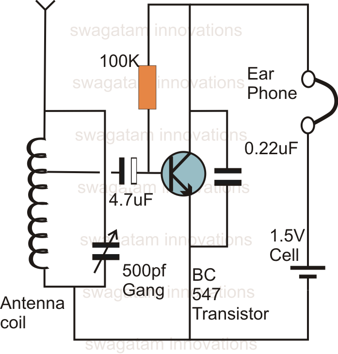
This is likely the simplest radio that can be assembled. The circuit design is straightforward enough to be completed in just a few minutes, allowing users to listen to their favorite programs immediately. The circuit of a single transistor...

This circuit utilizes the Mitsubishi M65830 Digital Delay chip, which has proven to be simple and effective for applications requiring a fixed delay. The serial data necessary for achieving various delay settings is not readily available and would significantly...
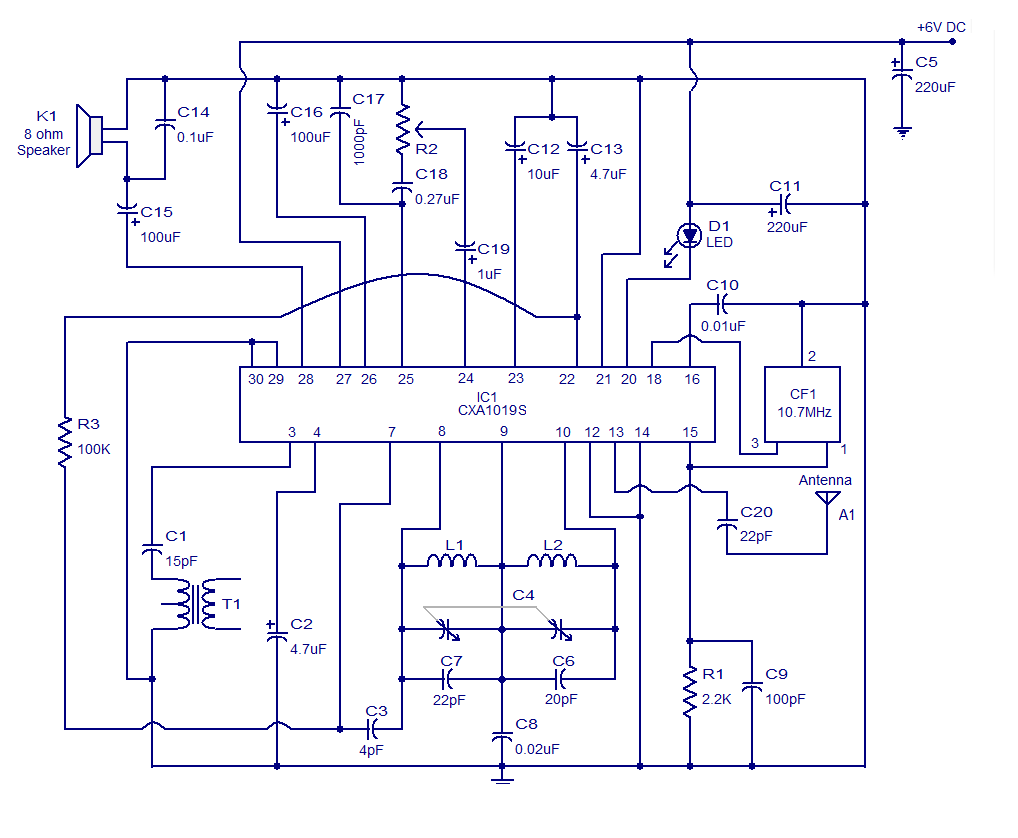
It is a high-quality FM receiver circuit based on the IC CXA1019. The CXA1019 is a monolithic silicon bipolar radio FM/AM receiver IC designed for Sony. The built-in circuitry within the CXA1019 includes an RF amplifier, mixer, oscillator, amplifier,...
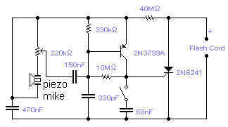
If you wish to take a picture of a fleeting event which generates a sound, you can do it with this sound activated trigger. It does not require any power supply: it feeds on the high voltage available on...