
UNDERVOLTAGE DISCONNECT SWITCH

The described circuit encompasses several critical functionalities, each contributing to the overall operation and efficiency of the system. The use of the TL494 as a PWM driver is particularly noteworthy, as it allows for precise control over the output voltage and current, essential for maintaining system stability and performance. The integration of error amplifiers A1 and A2 facilitates closed-loop control, ensuring that the system can adapt to variations in load and input conditions.
The tracking control circuit employing the BPY11 photosensitive batteries highlights an innovative approach to managing environmental interactions. By utilizing light-sensitive components, the circuit can autonomously adjust the operation of the electric motor based on ambient light levels, thus optimizing energy consumption and enhancing user experience.
Furthermore, the inclusion of protective measures, such as the diode group for transistor protection and the relay mechanism for power cut-off during voltage surges, underscores the design's commitment to reliability and safety. The incorporation of a music sound circuit adds an additional layer of functionality, allowing for user engagement through audio output.
Overall, the schematic illustrates a well-thought-out design that integrates various electronic components to achieve efficient control and operation of multiple systems, from refrigeration to environmental monitoring and audio playback. The combination of advanced components like the TDA5100 for radio transmission also indicates the potential for expanding the circuit's capabilities in communication applications.In the figure, the TL494 is used as the core to form the PWM driver and protection circuit, and the changing frequency is 50kHz. 115V output voltage is sent to P8 after stepping-down and isolating, then it is sent to TL494 error amplifier A1 after getting RMS by passing AD536, and it is used as the system`s closed-loop voltage control.
The current of push-pull inverter circuit is sent to control panel to do signal processing by P7 after passing current transformer sampler, then it is sent to the TL494 error amplifier A2 as the current-loop control system. TL494 outputs driver signal is amplified by passing P6, then it is sent to the main board. (View) The atmospheric pressure regulating equipments always use the tracking control circuit which is composed of the photosensitive battery BPY11.
When both of the two photosensitive batteries are irradiated by the light, there is no base current in the input transistor, they are similar to two phototransistors which are in the cut-off state, the electric motor has no current. If a photosensitive cell is not irradiated by the light, the corresponding edge half-amplifier will conduct, the electric motor turns left or right.
The last stage diode group can be used to protect the transistor to prevent the damage. The photosensitive signal can be adjusted by the 10M © potentiometer. (View) The circuit is as shown in the figure. It is composed of the relaxation oscillator, the light control pulse counting/decoding circuit, the SCR control motor speed control circuit, the music sound circuit and the AC step-down rectifier circuit. Under the strong light, the control circuit starts the fan to blow out the natural wind, and it broadcasts 16 world famous songs.
(View) The infrared receiving and motor driver circuit is as shown in figure 1, when there is no one, the infrared receiver receives the infrared beam which is from the other side. You can fix it one the wall by using the 60mm guide tube which can insert the infrared tube exactly (figure 3), the height is appropriate, and it aims at the opposite receiver, so the infrared ray is not easy to interfere another receiver.
The installation method is as shown in figure 4. The signal is amplified and filted by BG6, BG7 and CR to output the low level, the BG5 cuts off. (View) The Hualing BCD182 refrigerator control circuit is as shown in the figure. The button switches 1SB and 2SB are controlled by the refrigerating door and freezer dorr of the refrigerator respectively. When the door closes, the button switch closes too; When the door opens, the button switch cuts off. When the power is connected, the timing motor MT, the fan electromotor M1 and the compression motor M2 get power to operate.
The refrigerator starts to refrigerate. The current loop is: (View) The circuit principle is as shown in the figure. The 220V city electricity supplies the stable 12V operating voltage to the switch integrated circuit through the C1, VD1 and DW1, the partial voltage sampling circuit is composed of the VD3, R2 and RP1. When the city electricity voltage is normal, the DW2 can not conduct, the operating voltage of the TWH8778`s pin-5 is lower than 1.
6V, the relay J will not close, the city electricity supplies power to the socket CZ through J 1; when the city electricity voltage is higher than the normal value, the DW2 is conducted, the electric potential of the TWH8778`s pin-5 rises to 1. 6V, the IC turns, the pin-3 outputs the high level, the relay closes, the power supply of the electrical appliance is cut off to avoid the damage.
(View) The TDA5100 is designed as the Uhf radio transmitting circuit which is produced by the Siemens company, the internal structure is complex, the function is perfect, the sensitivity is high, the output signal amplitude is wide, the external components are few, the price is cheap, it is the superior performance transmitting circuit. (View) As the figure shows, it 🔗 External reference
Related Circuits
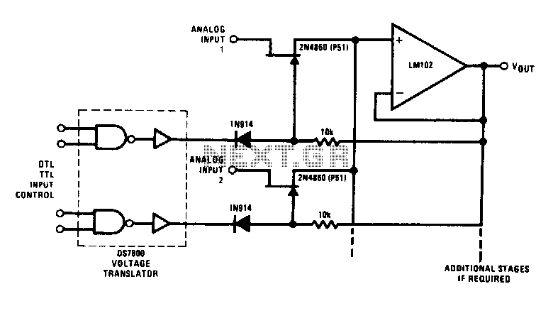
This analog switch utilizes the 2N4860 JFET, which features a low on-resistance of 25 ohms and minimal leakage current. The LM102 is employed as a voltage buffer in the circuit. Additionally, this configuration can be modified for use in...
This circuit will provide an indication whenever the input voltage differs from two defined limits, V1 and V2. The supply voltage, Vcc must be higher than the highest input voltage by at least 2 volts. One application here is...
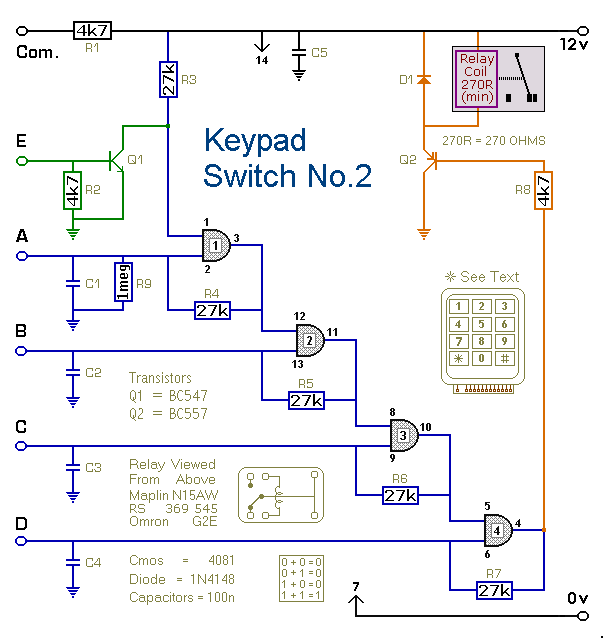
This is a simplified version of the 4-Digit Keypad Controlled Switch. The design has been modified to reduce circuit complexity and the number of components required. Consequently, the code is somewhat less secure, but it should be sufficient for...
A three-stage active Butterworth bandpass input filter is utilized in a radioteletype demodulator to differentiate RTTY tones from one another and from noise. The filter is centered at 2200 Hz and has a bandwidth of approximately 260 Hz, allowing...
In this modern era, any relationship characterized as master/slave may raise ethical concerns; however, for this circuit, it effectively illustrates its operation. The circuit detects the mains current supplied to a master device and controls the on/off state of...
The circuit automatically powers down a computer after Windows has been shut down, preventing users from forgetting to turn off their machines. Upon shutting down Windows, a click occurs after one second, disconnecting the PC from the mains supply....