
Telephone Line Indicator

A simple voltmeter can be constructed using an old moving coil instrument, which is a type of analog meter that measures electrical voltage. The moving coil mechanism operates on the principle of electromagnetic induction, where a coil of wire is placed in a magnetic field. When a voltage is applied across the coil, it generates a current that creates a magnetic field, causing the coil to move. This movement is proportional to the voltage and is indicated on a calibrated scale.
To build a voltmeter for monitoring the status of a telephone line, the following components are required: the moving coil instrument, resistors for current limiting, and possibly a rectifier if the voltage to be measured is alternating current (AC). The circuit should be designed to ensure that the input voltage does not exceed the maximum rating of the moving coil meter, which can be done by selecting appropriate resistor values to create a voltage divider.
The voltmeter can be connected in parallel with the telephone line, allowing it to measure the voltage present when the phone is in use or idle. The meter's needle will deflect in response to the voltage level, providing a visual indication of the line's status. This setup can be particularly useful for troubleshooting telephone lines or monitoring their operational status without the need for advanced equipment. Calibration of the voltmeter may be necessary to ensure accurate voltage readings, especially if the instrument is repurposed from another application.
Overall, the simplicity of using an old moving coil instrument for this purpose highlights the effectiveness of analog devices in providing straightforward visual feedback in electrical applications.With the aid of an (old) moving coil instrument it is very little effort to make a simple voltmeter that, at a glance, indicates the status of a telephone.. 🔗 External reference
Related Circuits
This is a simple 220V power interface circuit. This circuit is used as an interface for monitoring electrical devices and equipment using a computer. The 220V power interface circuit serves as a critical connection point between high-voltage electrical systems and...

The voltage Vc1 increases linearly when the pull-up resistor RA in the monostable circuit is replaced with a constant current source, resulting in the generation of a linear ramp. The figure illustrates the linear ramp generating circuit and the...
The hum noise is produced by an electronic device with improper design. To address this issue, it is essential to identify the source of the hum. This involves checking the grounding, cabling, casing, and other factors that may contribute...
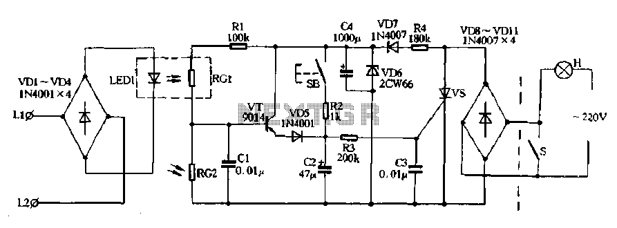
Diodes VD8 to VDI1 function as part of the main circuit isolation, with SCR serving as a composition control switch. The buck regulator circuit is composed of a stable orbital tube VD6 and a simple resistor-capacitor combination (C4). The...
Since the volume control is after the gain stage, the preamp can be easily overloaded. I tried to limit the input signal by mounting a 470 k resistor in series with the CD input. A voltage divider is formed...
The following circuit illustrates the A933 Transistor Telephone Listening Circuit Diagram. Features include the ability to tune from 88 to approximately 94 MHz and a simple design. The A933 Transistor Telephone Listening Circuit is designed to function as a radio...