
uninterruptible power supply
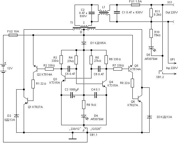
The 220 watts Uninterruptible Power Supply (UPS) is designed to provide reliable backup power during outages, ensuring that connected devices remain operational. The UPS typically includes a battery, inverter, and various control circuits. The battery stores energy, while the inverter converts the direct current (DC) from the battery into alternating current (AC), which is used by most electronic devices.
The circuit diagram of the UPS includes several key components. The battery management system monitors the state of the battery, ensuring it is charged properly and preventing over-discharge. A charging circuit, often utilizing a transformer and rectifier, converts AC mains power to DC for charging the battery.
The inverter section is critical to the UPS operation. It usually employs a combination of power transistors or MOSFETs configured in a push-pull or half-bridge arrangement to generate the required AC output. The control circuit regulates the output voltage and frequency, ensuring that the output remains stable under varying load conditions.
Additional features may include surge protection, overload protection, and indicators for battery status and load level. These components work together to create a robust power supply solution capable of supporting sensitive electronic equipment during power interruptions.
The overall design prioritizes efficiency and reliability, making it suitable for applications such as home offices, medical equipment, and data centers where continuous power is essential.220 watts Uninterruptible Power Supply power supply. Go to that page to read the explanation about above power supply related circuit diagram. 🔗 External reference
Related Circuits
This circuit above uses a 13 volt zener diode, D2 which provides the voltage regulation. Approximately 0.7 Volts are dropped across the transistors b-e junction, leaving a higher current 12.3 Volt output supply. This circuit can supply loads of...

Miniature isolated AC/DC power supply. This circuit employs a novel method to generate a fully isolated and regulated 5 volts at 30 mA from the 120 VAC power line. It utilizes two tiny SCRs that operate alternately. The miniature isolated...

The following circuit illustrates a 3V power supply designed for an RF remote control circuit. This circuit is based on the AT90S2323 integrated circuit (IC). Features include a data rate of 2400 bps. The 3V power supply circuit for the...
As an alternative to a bipolar transistor, a lamp flasher can be constructed using two power FETs. Similar to other flasher circuits, this circuit alternately switches the... The proposed lamp flasher circuit utilizes two power Field-Effect Transistors (FETs) to control...
The circuit diagram illustrates a voltage regulator designed from discrete components to meet specific voltage requirements. It provides two sets of component values for output voltages of 6.3 V (upper) and 12.6 V (lower). The components used include BC547...
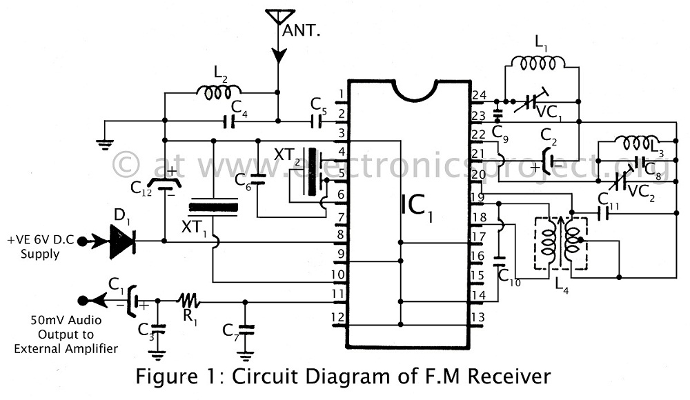
Communication in the FM band is straightforward. This circuit diagram illustrates a powerful FM receiver utilizing a single integrated circuit (IC) that receives frequencies from 88 MHz to 108 MHz within the FM band. The FM receiver circuit described operates...