
Stable Filament Power Supply Circuit
The voltage regulator circuit is constructed using two main types of bipolar junction transistors (BJTs): the BC547, which is an NPN transistor, and the BC557, which is a PNP transistor. These transistors are utilized to regulate the output voltage efficiently. The circuit is designed to handle two distinct output levels: 6.3 V and 12.6 V, which can be achieved by adjusting the component values accordingly.
The diode in the circuit serves a crucial role in protecting the transistors from reverse voltage, ensuring reliable operation. The use of a preset resistor allows for fine-tuning of the output voltage, providing flexibility in the regulation process. Capacitors are included in the design to filter out noise and stabilize the voltage output, enhancing the overall performance of the regulator.
Resistors are strategically placed to set the biasing conditions for the transistors, ensuring they operate within their optimal regions. The combination of these components creates a robust voltage regulation system capable of delivering stable output voltages for various applications in electronic circuits. The schematic provides a clear representation of the connections and values necessary to achieve the desired performance, making it a valuable reference for engineers and hobbyists alike.The Circuit Diagram shows a voltage regulator meeting these requirements that is built from discrete components. The two sets of component values are for a voltage of 6. 3 V (upper) and 12. 6 V (lower). Component: BC547 and BC557 Transistor, Diode, Preset, Capacitor, Resistor. [extremecircuits. net] 🔗 External reference
Related Circuits

The circuit employs a field-effect transistor (FET) at the input of a Schmitt trigger, allowing the use of a low-value capacitor. The trigger, controlled by Q1 and O2, exhibits a hysteresis of approximately 3V, regulated by a 3V zener...
This portable solar lantern circuit utilizes a 6 volt/5 watt solar panel, which is widely available. With this photovoltaic panel, an economical, simple, yet efficient and truly portable solar lantern unit can be constructed. The next essential component required...
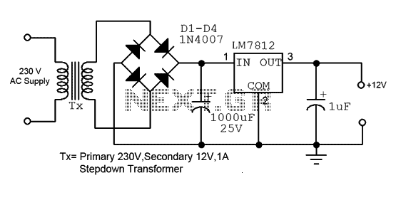
This is a straightforward 12V power supply circuit diagram. It features a fixed voltage output and is based on the LM7812 voltage regulator integrated circuit. The 12V power supply circuit utilizing the LM7812 voltage regulator is designed to provide a...
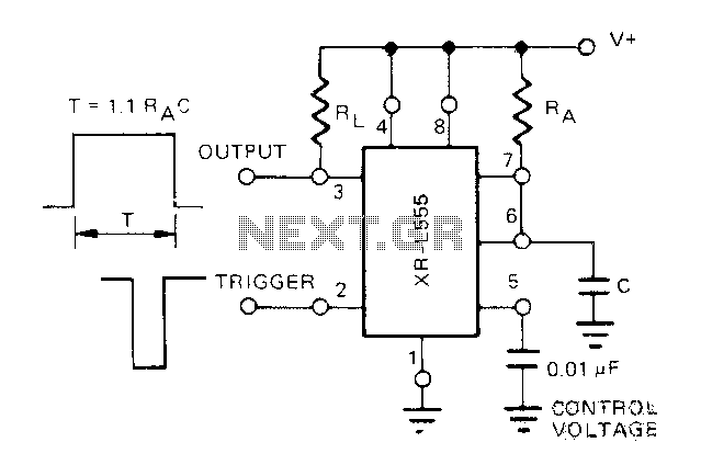
The Exars XR-L555 circuit has a typical power consumption of 900 W and operates with a power supply voltage of 5V. It is a micro-power circuit that can be used as a direct replacement for the standard 555 timer....
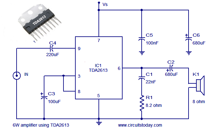
A simple and easy-to-build Hi-Fi audio power amplifier circuit is presented here. This 6-watt Hi-Fi audio amplifier circuit utilizes the TDA2613 integrated circuit (IC). The circuit design employs the TDA2613, which is a high-performance audio amplifier IC known for its efficiency...
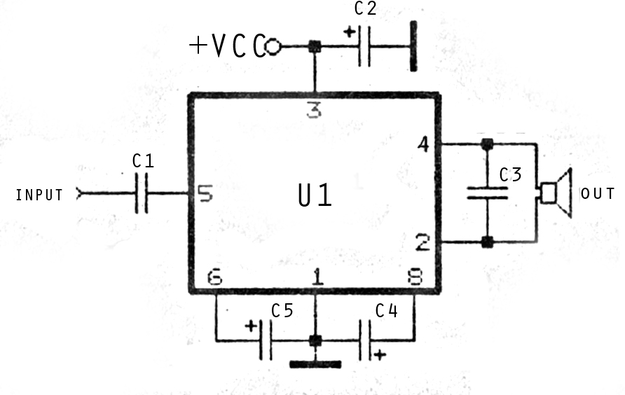
The image above depicts a miniature audio amplifier that is quite simple in design. A schematic for this audio amplifier is provided, which requires only a few components, as detailed in the accompanying diagram. This amplifier is inexpensive to...