
Unipolar Stepper Motor Driver
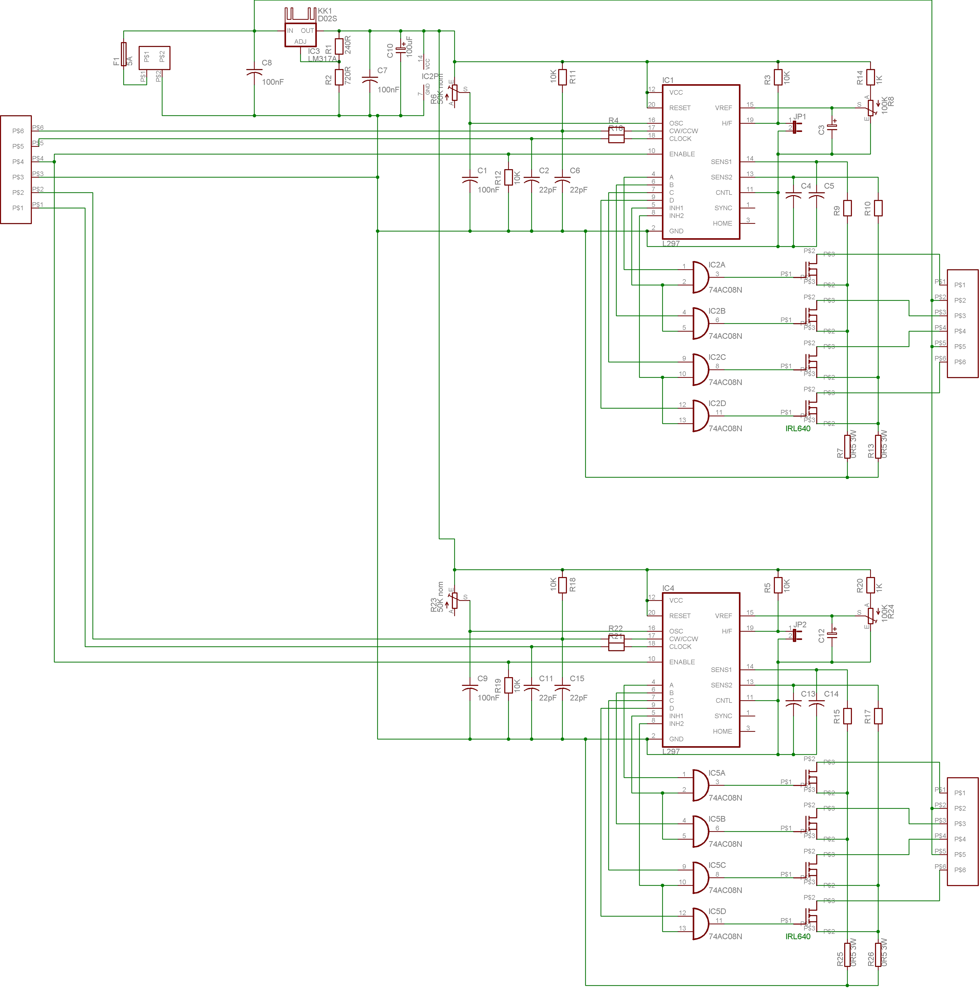
The stepper motor driver circuit is designed to efficiently manage the operation of 2-phase unipolar stepper motors by utilizing the L297 driver IC. The L297 is responsible for converting input signals into the appropriate sequence required to energize the motor coils, facilitating precise control over motor positioning. The implementation of current limiting is achieved through a feedback mechanism that monitors the voltage across a sense resistor. This resistor is strategically placed in series with the motor coils to provide real-time feedback of the current flowing through them.
The chopper control mechanism is a crucial aspect of this design, allowing for the dynamic adjustment of the current supplied to the motor coils. When the sensed current exceeds the predetermined threshold, the L297 interrupts the drive signal to the FETs, effectively reducing the current and preventing overheating. This feedback loop operates at a high frequency, ensuring that the current remains within safe operating limits while maintaining optimal performance.
Ethernet control integration enables remote operation of the CNC milling machine, allowing users to send commands and monitor the machine's status from a distance. This is achieved through a microcontroller that interfaces with the L297 and manages communication over the Ethernet network. The controller is programmed to interpret incoming commands, translate them into appropriate clock and direction signals, and relay these signals to the L297, ensuring accurate stepper motor operation.
The choice of FETs is critical to the success of this driver circuit. High-performance FETs are selected based on their ability to handle the required current without overheating and their capacity to withstand inductive spikes generated during motor operation. The absence of diodes in the circuit design minimizes additional heat generation and enhances efficiency. Careful attention to the FET specifications ensures reliable operation across a range of conditions.
Overall, this stepper motor driver design combines advanced current control techniques with robust logic and communication capabilities, resulting in a versatile solution suitable for a variety of applications, including CNC milling and other automation tasks.The purpose of this project was to develop a stepper motor driver for 2-phase unipolar stepper motors that has built in current control. The eventual target project for this driver is for my CNC milling machine that I am currently planning out.
This needs a few elements that are combined to provide a full driver. Once this is established the curre nt being supplied to the motor coils needs to be limitted in some way to stop melting anything. The obvious option here is to use a chopper circuit. Finally an intelligent controller is required to provide the correct number of steps for a required distance of travel. Many simply use a PC parallel port for this on CNC projects but I want this to be more of a stand-alone driver that can be used for other things.
Ideally I will include ethernet control so that I can run the CNC machine remotely from the comfort of my living room instead of the cold garage and negates the need for a dedicated control PC. The device is based around an L297 driver IC that performs the translation step (ie takes clock and direction input and generates the correct output sequence for driving the stepper) and has current limitting abilities.
Additional logic and driver circuitry is then added to drive the motor coils. Each motor driver is fully independant of the other drives and is controlled with its own clock and direction signals, has a seperate current limitter setting and should not interfere with each other. In reaching this final solution I went through many designs, some of my own, some through various searches on the net.
The final design is a combination of a few of the most common designs that can be found on the internet. One useful site I used is there are some good designs of stepper drivers and also a bulletin board where people share experiences and the owner gives great help.
A good resource for describing stepper motors is Jones on Stepping Motors The FETs must be chosen to allow the switching of each coil in the motor at full current. They must also be able to cope with the inductive EMF spike generated by the motor that could otherwise destroy the FET.
Some circuits show diodes being used to help control this spike and protect the FET, however in my experiments they caused more problems than they solved and generated a lot of heat. My circuit solution is simply to use FETs that are rated high enough to cope with this spike without the diode.
Approximetly I have spec`d this as around 4 times the supply voltage, however there may be a better calculation to work out the exact requirement. The next thing to consider is the logic level that will be used to turn the FETs on/off, referred to as Vgs (voltage across the gate-source junction).
In practice Vgs = Vcc - Vsense. ie The voltage across the FET gate is the supply voltage less the voltage across the sense resistor. The voltage across the sense resistor must therefore be controlled/limitted and the FET spec`d to work with `what is left`. The sense resistor voltage is limitted by the L297 device by means of the current limitting circuitry.
When Vsense (voltage across the sense resistor) reaches the reference voltage into the L297 Vref pin the inhibit output lines drop, in turn switching off the FETs and dropping Vsense. This sequence repeats giving an oscillating voltage across the sense resistor, this is known as the chopper action.
In practise when measuring this `chopped` voltage the reading is approx 2/3 of Vref, but for our calculations (giving us some VAT) it is best to use Vref itself in the calculations. So re-writing the previous formula: Vgs = Vcc - Vref. We set Vref between 0-1V and use a supply voltage of 5V for the logic. So Vgs = 5 - 1 = 4V. Now we need to refer to the datasheet of our FET and look at the Vgs vs Ids graph and ensure that when Vgs=4V the graph is not in its linear section (ie it has levelled out) and is therefore fully switched on.
This will give us 🔗 External reference
Related Circuits
The circuit depicted can be utilized to control a unipolar stepper motor equipped with four coils. This design is derived from an older fax machine. The circuit is capable of handling a motor current of approximately 500 mA per...
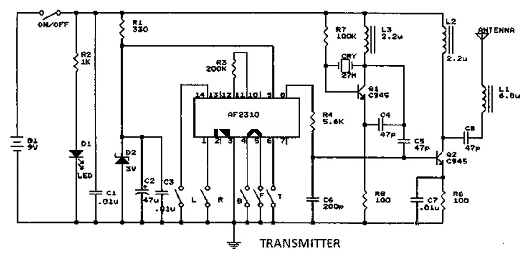
A radio control circuit designed for controlling small motors, similar to a car radio remote control toy, offers seven functions: forward, backward, left, right, left behind, right behind, and stop. The circuit requires a 27.9 megahertz frequency and a...
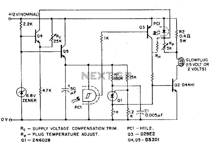
The circuit is designed for model airplanes, boats, and cars that utilize glow plugs for their miniature internal combustion engines (ranging from 0.1cc to 15cc). These engines are equipped with heavy batteries, high-tension coils, and capacitors necessary for classic...
4QD manufactures motor speed controllers, and all their H bridges utilize PWM. This is a simple switch circuit designed for reversing and stopping a motor without speed control. Two inputs, A and B, control the bridge. When both inputs...
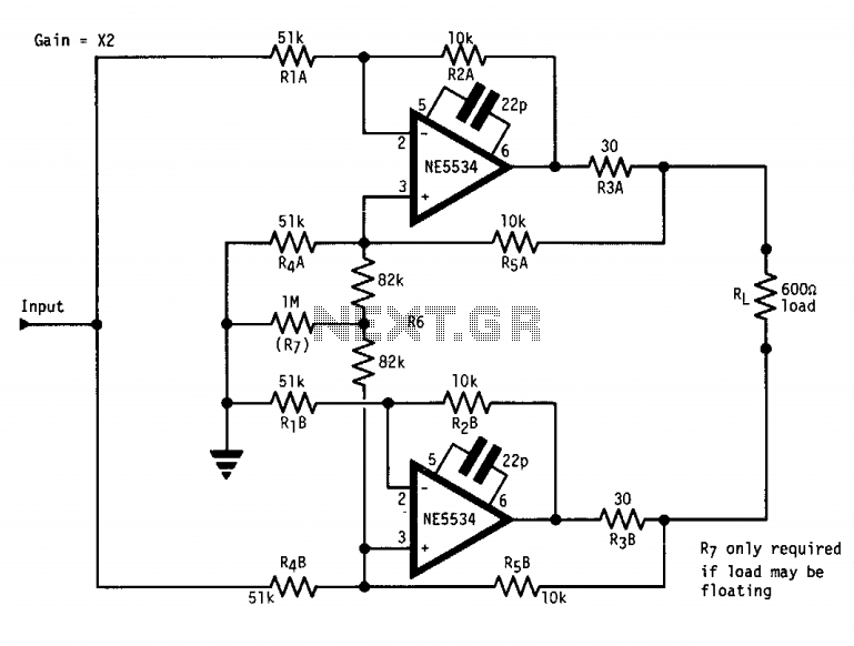
The circuit features a "floating" output, functioning similarly to an isolated transformer winding. The output amplitude remains constant regardless of whether the center or either end of the load is grounded. This is accomplished by ensuring that the output...
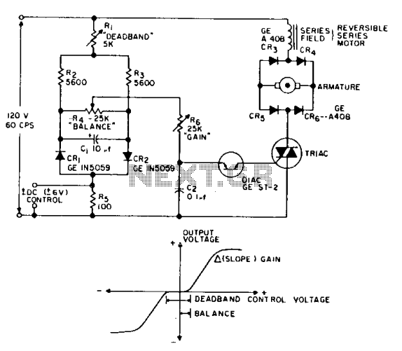
This is a positioning servo drive that includes adjustments for balance, gain, and deadband. In addition to receiving control from a DC signal, a mechanical input can be utilized for the balance control. Alternatively, this balance control can be...