
UPDATED ST-5 MAINLINE DEMODULATOR
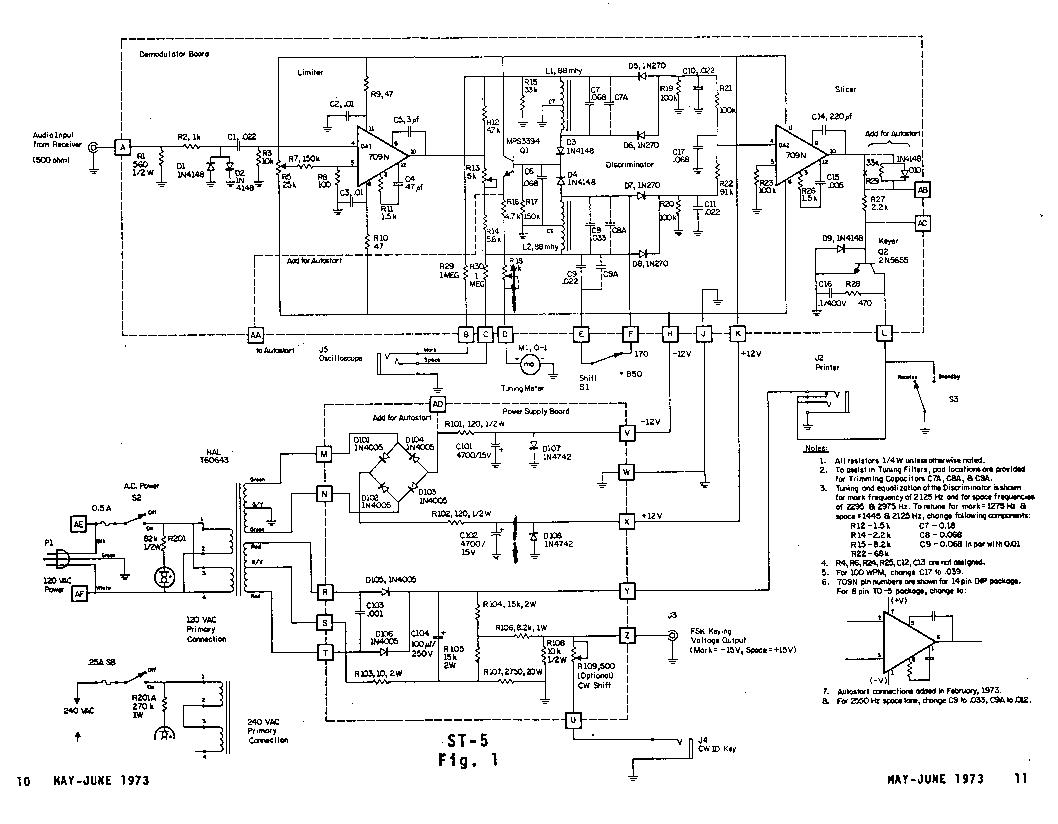
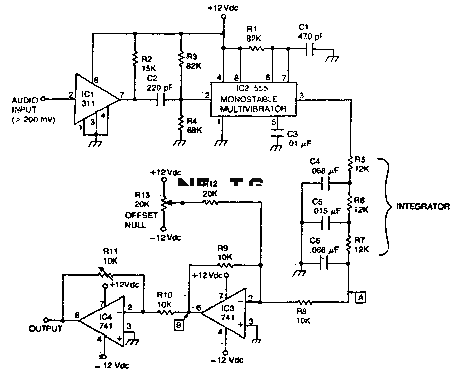
The ST-5 demodulator circuit is built around two operational amplifiers, which are crucial for signal processing. The first op-amp serves as an audio limiter, ensuring that the output signal does not exceed a certain amplitude, thereby preventing distortion. This is particularly important in RTTY applications where signal integrity is paramount. The second op-amp acts as a trigger stage, providing the necessary signals to drive the keyer, which is responsible for keying the transmitter on and off.
The design incorporates a regulated power supply, which is essential for stable operation of the circuit. The ±12-volt supply ensures that the operational amplifiers function within their optimal voltage range. The inclusion of a 175-volt loop supply allows for effective keying of the transmitter, which is a critical feature for RTTY communication.
The choice of components in the ST-5 circuit is deliberate, with the 709C op-amp selected for its high gain and bandwidth capabilities. This op-amp can handle signals well beyond the typical RTTY frequencies, making it versatile for various applications. The use of zener diodes provides an additional layer of protection, safeguarding the op-amp from potential damage due to high input levels.
Additionally, the circuit design allows for adjustments to accommodate variations in component values, particularly in the input stage. The inclusion of a potentiometer for balancing the offset input voltage demonstrates a thoughtful approach to ensuring consistent performance across different units.
Overall, the ST-5 represents a significant advancement in demodulator design for RTTY enthusiasts, providing a balance of simplicity and functionality. Its modular nature allows users to expand their systems as they gain experience and seek more advanced capabilities. The carefully designed filters further enhance its performance, making it a reliable choice for both beginners and seasoned operators in the RTTY community.The Mainline ST-5 was originally Introduced in the RTTY JOURNAL in May, 1970. It has rapidly become one of the most popular demodulators for RTTY. As back issues have been un available for some time, the original article is being reprinted. For those interested in 100 speed, change the 0. 068 capacitor on the input to the slicer to a 0. 039. A 741 m ay be used for the slicer if desired, in which case the 220 pf, 0. 005 Mfd. , and 1. 5K components are left off, as the 741 is internally compensated. Regulated voltage has been added, as shown. Keep in mind also that prices quoted were current at the time the article was originally written. Both Hal Communications and PEMCO, and possibly others, offer boards, components, kits and ready-to-use ST-5 units. Many newcomers to RTTY have complained that a current yet simple de modulator hasn`t been published for them to build.
The W2PAT unit in the ARRL handbook is nearly 15 years old. In 1964 an attempt was made to replace the W2PAT design with a modestly priced updated unit, the TT/L-1. This design. together with the subsequent TT/L-2 is now the standard of the serious RTTY enthusiast. However, the original goal was missed by a country mile, since the TT/L-2 costs over $160 just for parts and has l4 tubes.
The ST-3 was a successful solid- state design that introduced integrated linear operational amplifiers to RTTY. It was still moderately complex, however, and fell short of the goal to supply the beginner with something that could be built in a few hours.
While developing a unit based primarily on ICs to replace the TT/L-2, a very simple modulator with great potential was developed: the ST-5. As with any simple circuit, the cost of the power supply is out of proportion with the rest of the unit.
At 1970 prices the ST-5 costs only $14. 50 less loop supply and a plus-minus 12-volt supply ($11). The total cost of $33 is not overly impressive until you realize this unit can, if desired, be used as a building block for the more exotic ST-6. Almost every component used here can be used in that unit. The ST-5 is a basis from which the beginner can expand - it`s not just a collection of parts that will find no further use when he is ready to broaden his horizons to more sophisticated equipment.
The ST-5 uses two operational amplifiers (Fig. 1 shown at end of this article). One is an audio limiter, and the other is a trigger stage to drive the keyer. It has a 175-volt loop supply of the same type used in the TT/L, which provides plus-minus voltages for keying a transmitter and also features narrow-shift cw identification. Finally, the ST-5 has a symmetrical plus-minus 12-volt power supply. The 709C op amp has over 90-dB gain and is good to over 10 MHz. It makes an ideal limiter. The zener diodes on the input don`t assist in the limiting; they merely protect the 709C against damage in the event of excessive audio input (hardly likely but worth the protection).
The limiter puts out square waves and is so powerful it starts working on input signals as low as 200 mV. The 25k pot merely balances the small offset input voltage for maximum gain. This voltage varies slightly from one unit to another, so a control pot was added rather than a fixed resistor, which many units use.
It`s difficult to use the same value inductor with different capacitors and expect to obtain two similar filters of equal characteristics. To get similar band-width, voltage output, noise response, etc. , some loading is necessary. Most simple demodulators merely balance the voltage or ignore all the problems completely. Without belaboring the point, it`s not a simple job to get all these factors to balance suitably; but it is possible, and the Mainline units all have filters that have been designed with care.
The ST-5 offers a choice of the 2125-2975 mark and space tones (considered standard), or the 1275-2125 low tones necessary in some modern receivers. (Actuall 🔗 External reference
Related Circuits
Replacing the LC modulation circuit with an active filter allows for the elimination of large and costly inductance coils in frequency shift key control demodulators. This approach not only reduces the size of the circuit but also enhances the...
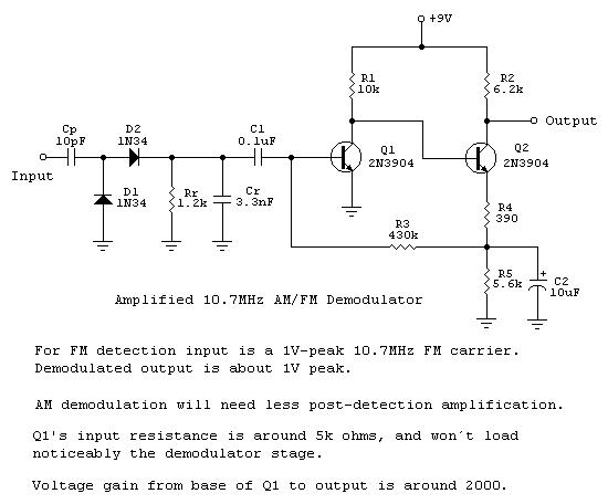
Frequency-to-voltage converters are integral components in various instrumentation circuits and are also utilized in radio applications as FM demodulators. A notable configuration for these applications is the Diode Charge Pump circuit (DCP), which additionally serves as an AM detector....
A Phase Locked Loop (PLL) can be utilized to create a Frequency Modulation (FM) demodulator. The PLL circuit tracks the input frequency by adjusting the voltage input of a Voltage-Controlled Oscillator (VCO). The Phase Locked Loop (PLL) is a critical...
The circuit recovers an FM audio signal that varies from less than 1 kHz to about 10 kHz. The circuit is designed to demodulate frequency-modulated (FM) audio signals within the frequency range of less than 1 kHz to approximately 10...
The FSK demodulator is an electronic device that converts the FSK signal into a serial digital signal. FSK modulation is utilized to transmit digital serial data. The FSK (Frequency Shift Keying) demodulator serves a critical function in digital communication systems...
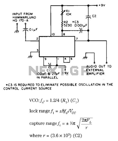
Useful for narrowband frequency modulation (NBFM) reception on older shortwave receivers that lack this capability, this circuit employs a phase-locked loop (PLL) integrated circuit, specifically the N565N. It was originally designed for use with an old Hammarlund HQ-170 receiver,...