
Telemetry demodulator
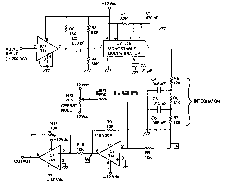
The circuit is designed to demodulate frequency-modulated (FM) audio signals within the frequency range of less than 1 kHz to approximately 10 kHz. The primary function of this circuit is to extract the original audio information from the modulated carrier wave, allowing for playback or further processing of the audio signal.
To achieve this, the circuit typically includes several key components: an antenna for receiving the FM signal, a radio frequency (RF) amplifier to boost the signal strength, and a demodulator stage that converts the FM signal back into an audio frequency (AF) signal. The demodulation process often employs a phase-locked loop (PLL) or a discriminator circuit, which can effectively track the variations in frequency of the incoming FM signal.
After demodulation, the audio signal may undergo additional processing, such as filtering to remove any residual RF components and amplification to bring the signal to a suitable level for output. The final output stage may include a low-pass filter to ensure that only the desired audio frequencies are passed through, effectively eliminating any high-frequency noise that may have been introduced during the transmission.
The circuit's design must also consider factors such as signal-to-noise ratio (SNR), distortion, and the overall bandwidth to ensure high-quality audio reproduction. Proper layout and component selection are critical to minimize interference and maintain signal integrity throughout the circuit.The circuit recovers an FM audio signal that variesfrom less than 1 kHz to about 10 kHz. 🔗 External reference
Related Circuits
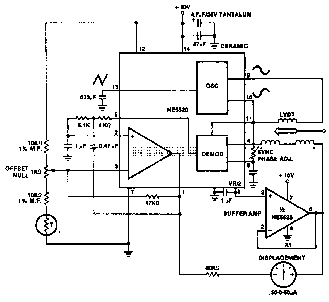
A simple motion transducer can be constructed using the provided circuit. The output is biased to one-half of the supply voltage, necessitating special interface circuitry for signal readout. One straightforward method involves utilizing a zero-center meter in a bridge...
The advantages of synchronous reception of AM signals are well recognized, including high selectivity, linearity of detection, and a lower noise level at the output compared to other reception methods. The circuit diagram is illustrated in Figure 1. The...
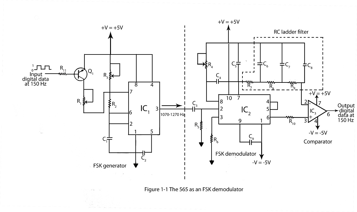
The frequency shifting keying technique is utilized to transmit binary data. The circuit diagram includes a description of an FSK demodulator that employs the 565 integrated circuit for frequency shift keying. The frequency shift keying (FSK) technique is a form...
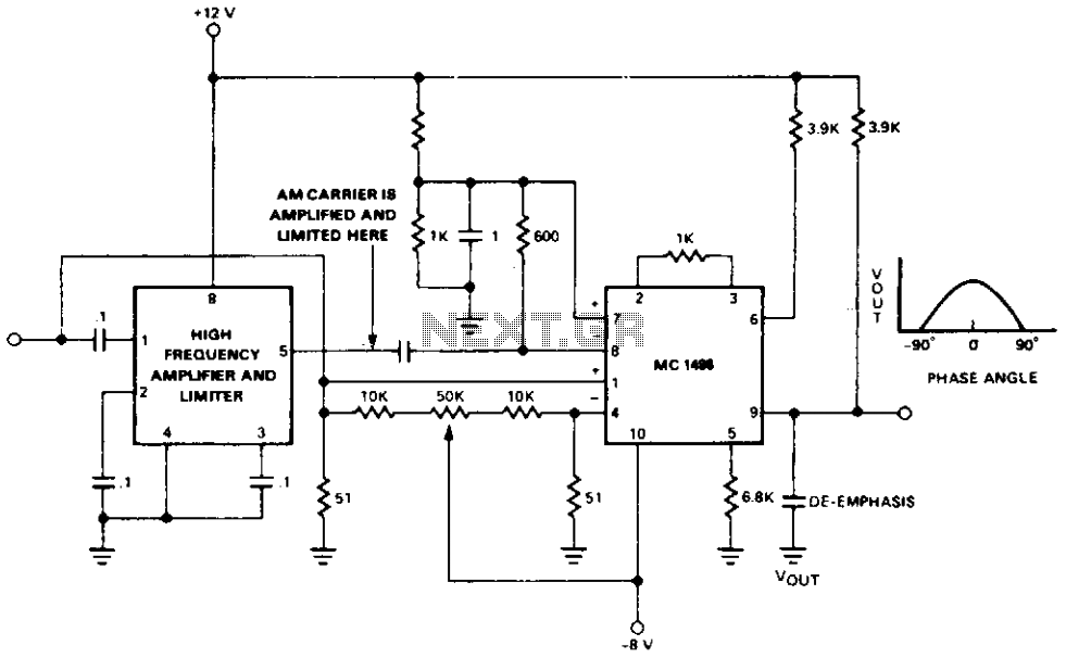
Amplifying and limiting the AM carrier is achieved through the IF gain block, which provides a gain of 55 dB or higher with a limiting level of 40 µV. The limited carrier is then fed to the detector at...
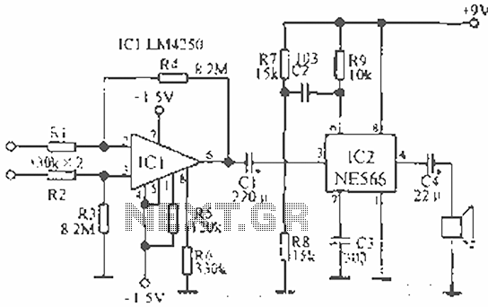
The circuit is designed for teaching demonstrations or experiments to hear the electrocardiogram (ECG) signal voltage. The ECG signal voltage is amplified by the LM4250 operational amplifier, which is connected to a voltage-controlled oscillator (NE566) to modulate the oscillator...
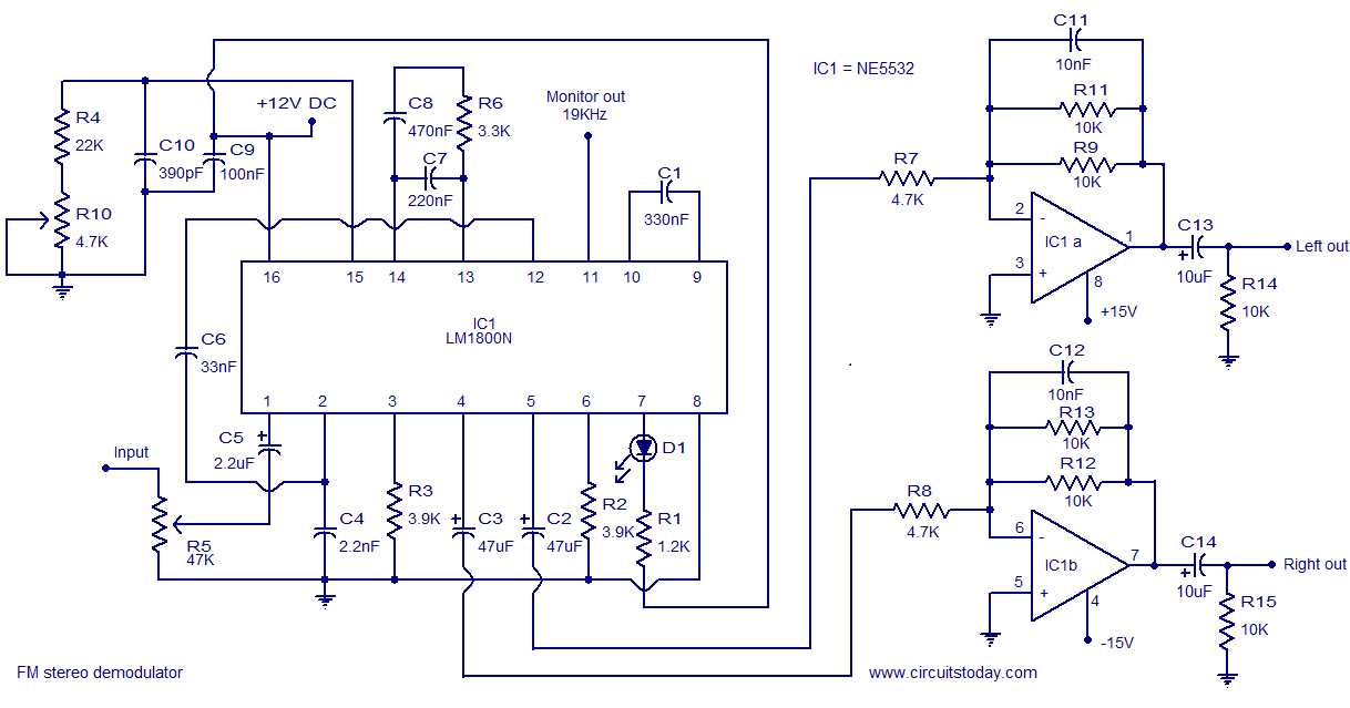
The LM1800 is an integrated FM stereo demodulator IC that incorporates several beneficial features, enabling the design of a high-quality FM stereo demodulator system with excellent sound quality. The LM1800 utilizes phase-locked loop technology to regenerate the 38 kHz...