
UPS Schematic
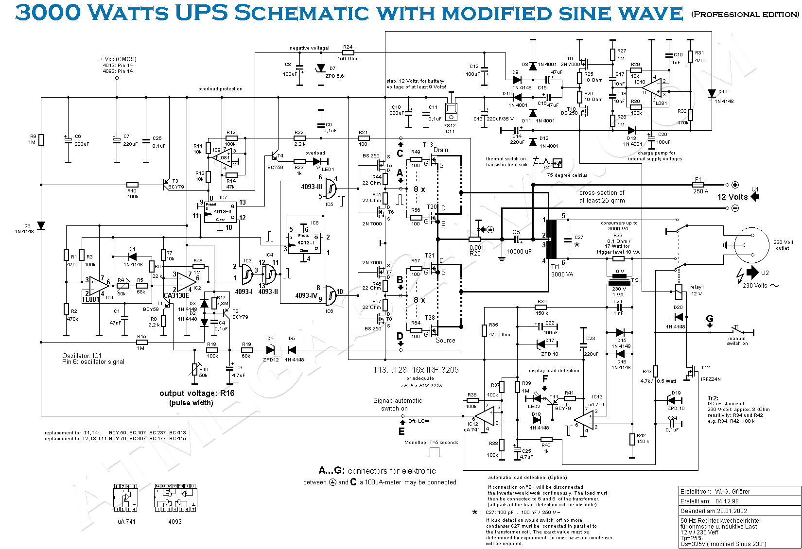
The schematic circuit diagram for a 3000 Watts Uninterruptible Power Supply (UPS) is designed to provide reliable backup power in the event of an electrical outage. This UPS is capable of handling loads up to 3000 Watts and can be adapted to support a 1000 VA load with minor modifications to the circuit components.
The primary components of the UPS include an inverter, battery bank, charger, and control circuitry. The inverter converts the DC voltage from the battery bank into AC voltage suitable for powering standard household or industrial appliances. The battery bank typically consists of lead-acid or lithium-ion batteries, which store energy for use during power interruptions.
The charger is responsible for maintaining the battery bank's charge level when mains power is available. It ensures that the batteries are charged efficiently and safely. The control circuitry monitors the input voltage, output voltage, and battery status, allowing for seamless switching between mains power and battery power.
In the event of a power failure, the control circuitry detects the loss of input voltage and activates the inverter, supplying power from the battery bank to the connected load. The UPS may also include additional features such as overload protection, short-circuit protection, and surge protection to safeguard both the UPS and the connected devices.
For the adaptation to a 1000 VA system, modifications may include adjusting the transformer rating, changing the battery capacity, or altering the inverter circuit to accommodate the lower power requirements. This flexibility allows users to customize the UPS to meet their specific needs while maintaining a high level of performance and reliability.
Overall, the UPS schematic circuit diagram serves as a crucial blueprint for constructing a robust power backup solution, ensuring continuous operation of essential equipment during power outages.UPS Schematic Circuit Diagram for 3000 Watts UPS It can also work for 1000 VA with minor modifications. 🔗 External reference
Related Circuits
Approximately 20 years ago, it was common to encounter small key-holders that emitted an intermittent beep for a few seconds after the owner whistled. These devices utilized a specialized integrated circuit (IC) and were not suitable for home construction....
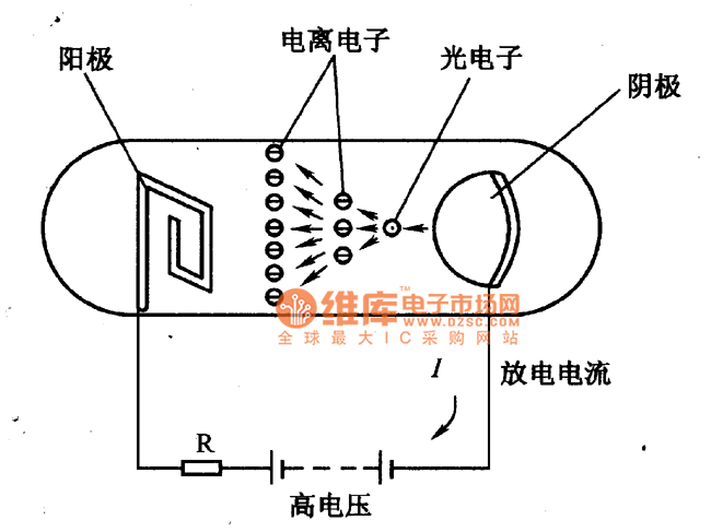
The figure illustrates a schematic circuit of a UV sensor. When voltage is applied between the cathode and anode, and UV radiation passes through the quartz glass tube on the cathode's optical surface, the cathode material, which is coated...
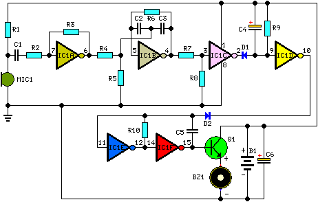
This is a diagram of a car audio active loudspeaker utilizing the LF353 operational amplifier from National Semiconductor. For optimal performance, the NE5532 is recommended to split the audio signal into three frequency bands using an active filter. The...
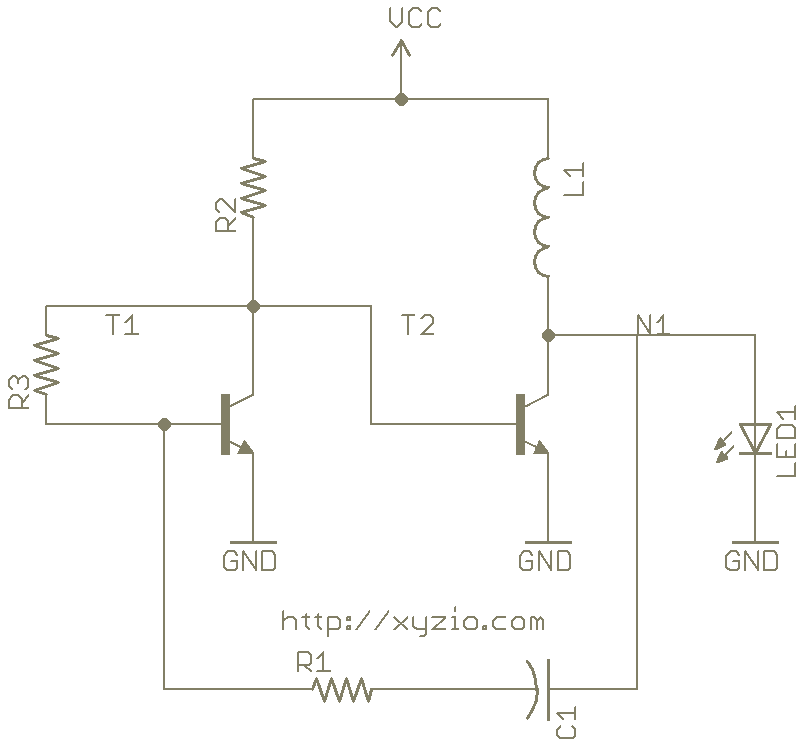
How a Joule Thief Works. The increase and decrease across R3 causes T1 to switch on and off. As T1 toggles, the voltage across R2 varies. This change in voltage at the base of A Joule Thief is a...
This document outlines a basic fire alarm circuit utilizing an LDR (Light Dependent Resistor) for fire detection. The circuit is designed to generate an audible alarm in response to smoke, which affects the LDR's resistance. In the absence of...
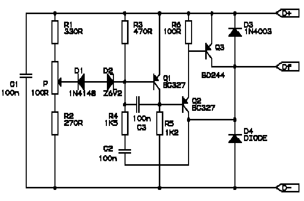
Correctly adjusted, the voltage on the pot wiper is slightly less than half D+ (appx. 0.47*D+) and Q1 will conduct if (D+)-(Vp) > 6.2 + 0.7 + 0.7, or 0.53*(D+) > 7.6V, (D+) > 14.3V. If D+ is lower...
Warning: include(partials/cookie-banner.php): Failed to open stream: Permission denied in /var/www/html/nextgr/view-circuit.php on line 713
Warning: include(): Failed opening 'partials/cookie-banner.php' for inclusion (include_path='.:/usr/share/php') in /var/www/html/nextgr/view-circuit.php on line 713