
USB-Atmel External 3.3V Level Converter
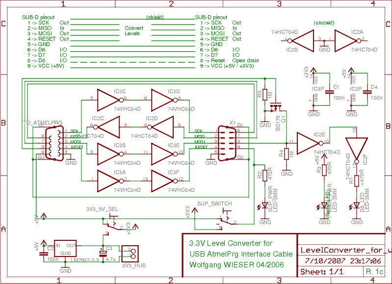
In this circuit design, the arrangement facilitates programming of devices that operate at different voltage levels by utilizing a combination of logic level converters and power management switches. The 74VHC04 or 74VHC14 integrated circuits serve as the core components for level shifting from 5V to 3.3V. These components are selected for their tolerance to higher voltage levels while maintaining compatibility with lower voltage outputs.
The LM2937 LDO regulator plays a crucial role in generating the necessary 3.3V output from the supplied 5V, ensuring that the circuit can effectively interface with both 3.3V and 5V devices without risk of damage or signal misinterpretation. The inclusion of two switches allows for user-defined configuration of the output logic levels and power supply options, enhancing the circuit's versatility.
The primary output logic level selector switch simplifies the process of toggling between the two voltage levels, while the power supply options switch provides flexibility for powering the external device. This is particularly useful in scenarios where the device may be self-powered or requires specific voltage levels for operation. The indication LEDs (green for MAIN_PWR and red for SUP_PWR) provide visual feedback on the power status of the circuit and the connected device, ensuring that users can easily monitor the operational state.
Overall, this circuit design demonstrates a well-thought-out approach to managing voltage levels and power supply configurations, making it suitable for a variety of programming applications involving mixed-voltage devices.In order to programm devices which run at 3. 3V (either SPI-based ones like AVRs or JTAG-based ones like CPLDs), the input and output signal levels need appropriate level conversion (or level shifting) because a 5V input may not see HIGH at 3. 3V and a 3. 3V device may be damaged by a 5V signal. No tristate outputs: If in your design, the programming lines are multiplexed with other interface logic, then you need to disconnect the plug after programming. In order to convert 5V to 3. 3V, I use a 74VHC04 (or alternatively a 74VHC14) which has 5V-tolerant inputs when powered at 3. 3V to get the appropriate 3. 3V output levels. For 3. 3V to 5V level shifting, a 5V-powered 74HCT04 (or alternatively a 74VHCT04) will do the trick since the `T` variants have lowered thresholds for TTL compatibility. (It turned out experimentally that a 74HCT14 Schmitt trigger works as well but looking at the input levels in the data sheet, I must discourage its application.
) The level converter requires a 5V supply voltage but no 3. 3V supply since it generates the 3. 3V itself from 5V using the LM2937 LDO regulator. Using the two switches on the board, all important power configuration options can be realised: Primary output logic level selector. This switch allows to select the secondary logic level voltage. For normal 5V to 3. 3V level shifting, select the 3. 3V from the LDO (lower position). When choosing the 5V line (upper position), level shifting will switched off since both input and output logic levels are then 5V.
This switch should have 2 positions. Selects the power supply options for the device to be programmed. This switch should have 3 positions: In the upper position, the external device to be programmed will be supplied with 5V, in the lower position it will be supplied with output logic level voltage (as chosen by 3V3_5V_SEL) and in the middle position, the external device is not supplied and has to run self-powered. Hence, you always enable the S2 switch on the USB-AtmelPrg circuit to get the level shifter powered (check the green LED MAIN_PWR as power indicator).
Then, from the point of view of the device to be programmed, the SUP_SWITCH acts like the S2 switch on the USB-AtmelPrg with the additional feature that it can provide 5V or 3. 3V via pin9. Check the red SUP_PWR LED to see if the device to be programmed has its own power supply before switching on the SUP_SWITCH.
🔗 External reference
Related Circuits
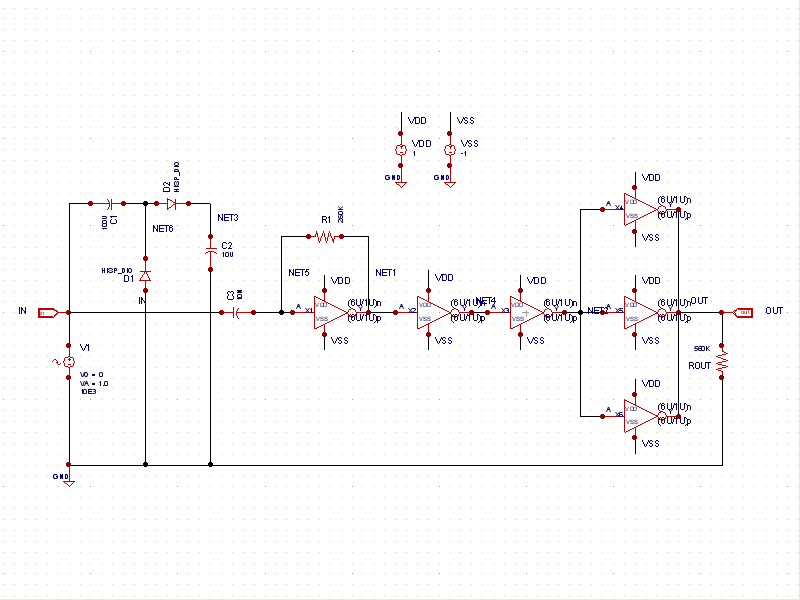
This schematic example demonstrates a sinusoidal voltage input at a frequency of 10 kHz, which is converted to a square wave using an inverter-based circuit. The VDD and VSS rails are connected to +1V and -1V, respectively. The control...
The image depicts an ultrasonic liquid level indicator circuit. This circuit consists of an ultrasonic transmitter circuit and a receiver circuit. The ultrasonic transmitter circuit includes a 555 timer, resistor R1, variable resistor W1, capacitor C1, and the ultrasonic...
The circuit diagram features two LT1398 operational amplifiers from Linear Technology, which are utilized to generate buffered color-difference signals from RGB (red-green-blue) inputs. The red (R) input is received through a 75-ohm coaxial cable and is directed to the...
This document presents a straightforward and practical schematic for a 12V to 3V converter circuit. The output current of the circuit is approximately 1A. The 12V to 3V converter circuit is typically designed using a linear voltage regulator or a...
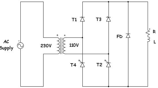
Controlled rectifiers are line-commutated AC to DC power converters that convert a fixed voltage and fixed frequency AC power supply into a variable DC output voltage. The input supply provided to a controlled rectifier is an AC supply with...
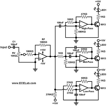
The simple circuit for converting an audio signal. The circuit basically consists of a buffer/amplifier stage and three filter circuits. The audio signal conversion circuit is designed to process audio signals efficiently while maintaining signal integrity. The circuit architecture includes...