
usb charger

The portable battery-powered USB charger circuit based on the LM7805 voltage regulator is designed to convert a higher voltage from a battery source into a stable 5V output suitable for charging USB devices. The primary component, the LM7805, is a linear voltage regulator that provides a fixed output voltage of 5V with a maximum output current of 1A, making it ideal for powering USB devices such as smartphones and tablets.
The circuit typically consists of the following essential components:
1. **LM7805 Voltage Regulator**: This component regulates the input voltage to a stable 5V output. It has three terminals: input, ground, and output. The input terminal connects to the positive terminal of the battery, while the ground terminal connects to the negative terminal.
2. **Input Capacitor (C1)**: A capacitor, usually around 0.33µF, is connected between the input terminal of the LM7805 and ground. This capacitor helps filter out high-frequency noise from the power source, ensuring stable operation.
3. **Output Capacitor (C2)**: A capacitor of about 0.1µF is connected between the output terminal of the LM7805 and ground. This capacitor improves transient response and stability of the output voltage.
4. **Battery Source**: The circuit can be powered by various battery types, such as lithium-ion or NiMH batteries, typically providing a voltage range from 7V to 35V, which is suitable for the input requirements of the LM7805.
5. **USB Connector**: A standard USB A or micro USB connector is used at the output to connect the device being charged. The output from the LM7805 is directly connected to the VBUS and GND pins of the USB connector.
The design emphasizes simplicity and efficiency, requiring minimal additional components. The use of the LM7805 ensures that the output voltage remains stable, even with varying input voltage levels, making it suitable for portable applications where battery voltage may fluctuate.
This circuit can be assembled on a small PCB or a breadboard, allowing for easy prototyping and testing. Proper heat dissipation measures, such as attaching a heatsink to the LM7805, may be necessary if the circuit operates near its maximum current capacity for extended periods. Overall, this portable USB charger circuit provides a reliable and straightforward solution for charging devices on the go.Portable battery powered USB charger circuit or schematic using IC LM7805. The circuit require only few components. .. 🔗 External reference
Related Circuits
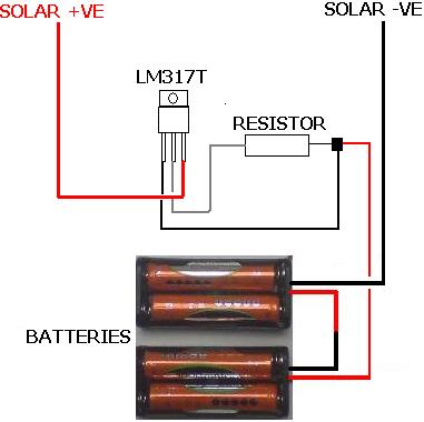
The following circuit illustrates the LM317T IC designed for a solar battery charger circuit diagram. Features include a simple circuit suitable for AA and AAA rechargeable batteries. The LM317T is a versatile linear voltage regulator that can be used in...
Build an interface board to connect scientific equipment, specifically a pair of photovoltaic tubes, to a personal computer for acquiring measurement results. The signal properties include two channels with a common ground, a one-second acquisition time, and a maximum...
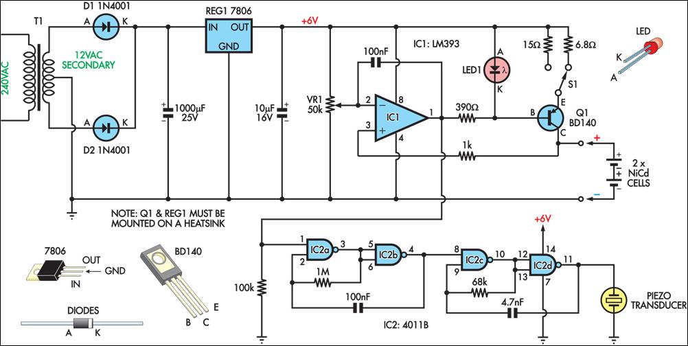
This circuit charges two NiCad cells with a constant current and features dual charging rates, voltage cutoff, and an audible alarm. The circuit is powered by a 12VAC center-tapped mains transformer, along with two rectifier diodes (D1 & D2)...
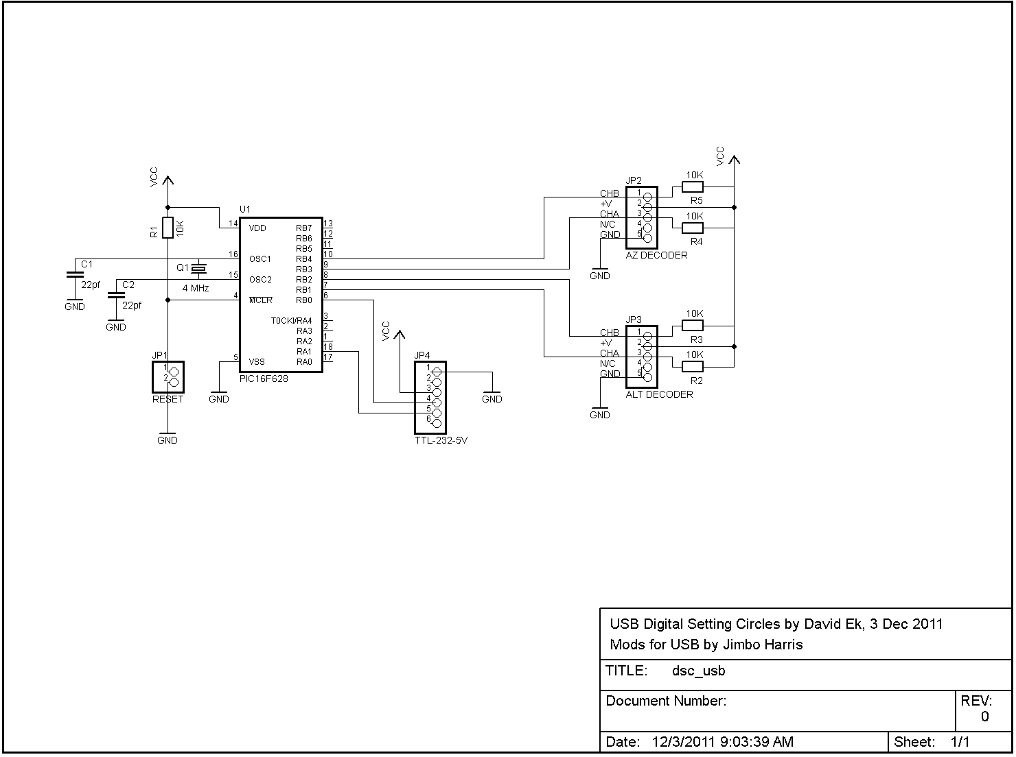
The serial version of the DSC circuit described in these pages is easily adaptable for use with a USB-serial conversion cable. FTDI manufactures the TTL-232R-5V cable, which converts TTL-level serial data directly from the PIC to USB for connection...
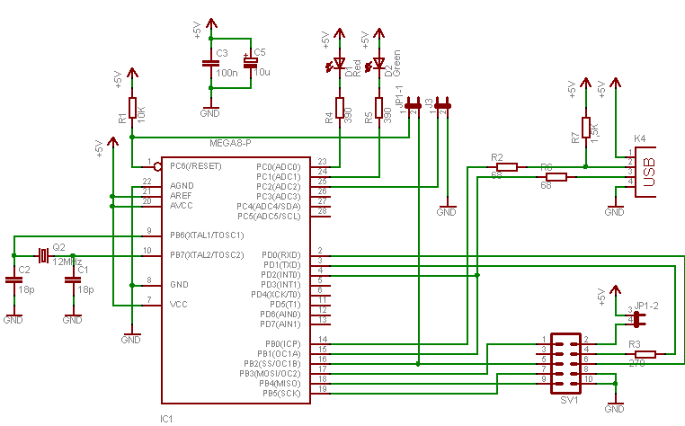
To program an AVR microcontroller using a USB port instead of parallel or serial interfaces, USBasp is the most suitable option. A circuit diagram for USBasp is available. The procedure for burning the hex file includes installing avrdude (WinAVR),...
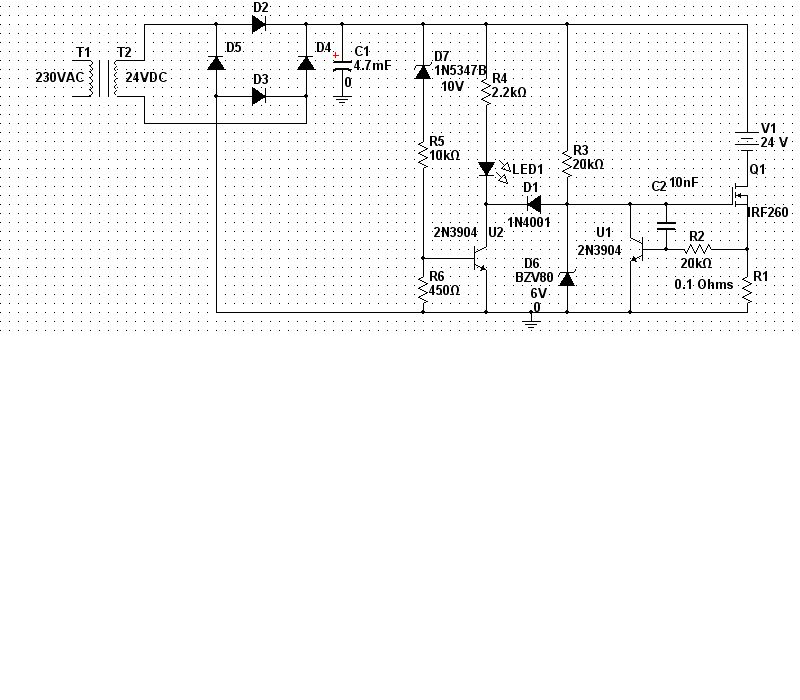
A 240/24Vac (rms) transformer is utilized, which after rectification and filtration provides approximately 30Vdc. It is crucial to select the transformer and diode ratings appropriately to meet the required specifications. In the current limiting stage, transistor U1, Q1, and...
Warning: include(partials/cookie-banner.php): Failed to open stream: Permission denied in /var/www/html/nextgr/view-circuit.php on line 713
Warning: include(): Failed opening 'partials/cookie-banner.php' for inclusion (include_path='.:/usr/share/php') in /var/www/html/nextgr/view-circuit.php on line 713