
USB phone charger
The portable phone charger circuit integrates several key components to achieve its functionality. The TPS61032 step-up converter is at the heart of the design, providing the necessary voltage boost to charge modern devices. The converter's synchronous design enhances efficiency by eliminating the need for external diodes, which can introduce voltage drops and additional heat generation. The output voltage regulation is crucial for compatibility with various devices, and the inclusion of the switch for the D+ and D- lines allows for flexibility in charging modes, accommodating different charging protocols.
The low battery detection circuit is implemented using a simple LED indicator, which offers a visual cue to the user regarding the battery status. The choice of a P-channel MOSFET for driving the LED allows for low power consumption while providing adequate brightness. The design considerations for the PCB, including the size limitations imposed by the manufacturer and the need for careful component placement, reflect practical engineering challenges that were successfully addressed.
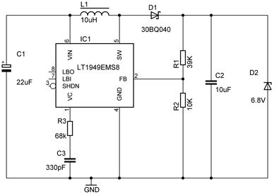
Overall, the charger is designed for ease of use and efficiency, making it suitable for charging a variety of devices while maintaining a compact form factor. The attention to detail in component selection, circuit design, and PCB layout contributes to the reliability and performance of the charger, ensuring that it meets the demands of users seeking a portable charging solution.A portable phone charger for a Siemens mobile phone. Since I don`t use that phone anymore and recent phones can usually be charged with a USB connector I built a new version of the charger. This time with a proper PCB, a USB connector and a higher current capability. Just as the previous charger it is basically just a step-up conve rter largely built according to the datasheet. In this case I used the TPS61032 because of its high efficiency, low minimum input voltage (1. 8V) and high internal switch current (4A). I wanted the converter to be able to deliver about 1A at 5V, which requires an average input current of 2. 5A at 2V input but the peak current can be much higher. The converter is synchronous, which eliminates the need for an external Schottky diode (and its relatively large power loss).
This version also includes a low battery led which turns on when the input voltage is around 1. 95V. At this voltage the batteries will soon drop out. The step-up converter can run down to 1. 8V but usually when the two batteries are at this voltage there is not much energy left and they will soon drop even lower than 1. 8V. Batteries with high internal resistance may come very close to 1. 95V even when not empty, so make sure you use good quality rechargeable batteries with low internal resistance.
Because the low battery output of the converter can only sink up to 100 µA (active low) I added a small P-channel mosfet to be able to drive a LED from it. I also added a little switch that determines what`s connected to the D+ and D- data pins on the USB connector.
It switches between two common configurations for USB chargers. One is around 2. 0V and 2. 75V on D+ and D- respectively, which is what Apple`s iPhone wall charger does (as well as the Belkin ones). An iPhone will charge at 1A with this configuration. See also the mysteries of Apple device charging by ladyada who figured it all out. The other setting connects D+ and D- with a 100 © resistor. This is according to the USB battery charging specification, which requires a resistance of less than 200 © between the data pins to indicate the USB port can be used for charging.
In fact the standard states a maximum of 1. 5A which is more than this charger can handle but most phones will use a current below 1A. An iPhone can also detect this setting, but will charge at 500mA instead. I built the charger for my iPhone, effectively having a switch between 1A and 0. 5A charging current. That might not be the case on other phones but most phones will charge with at least one of the switches. I`ve tried it out on an Android phone and this also works, although I haven`t measured the current (I believe it is around 700 or 800mA).
All the parts from the resistors to the screws are from digikey, you can lookup the part list below. Total cost based on PCBs and parts for 5 pieces is around ‚¬20 per charger. The PCBs are made by iTeadStudio for about ‚¬10 for 10 pieces (I actually got 12). Quality is good, silkscreen is a little thick on some of the boards and the HASL finish is not as flat as ENIG but perfectly usable. When the boards were built I found out the battery connector pins aren`t actually centered which I foolishly assumed they were but that could be fixed easily by bending them a little.
The boards fit nicely onto the battery connector. If you`re wondering why the board doesn`t extend al the way to the edges, it is because iTeadStudios has a size limit of 5x5cm for the cheapest price category, and paying twice as much (10x10cm) wasn`t worth it. I used a hex nut as a spacer since the USB receptacle needs a little room for its through hole pins. In fact I had to clip the pins a little to reduce the spacing between the battery holder and the PCB, but it`s still soldered rock solid.
The regulator has a heat transfer pad on the bottom so you really need hot air or a reflow oven to solder it, or maybe you could get 🔗 External reference
Related Circuits
This is a simple microphone preamplifier circuit designed for use between a microphone and a stereo amplifier. This circuit is compatible with standard home stereo amplifier line, CD, aux, and tape inputs. It can accept both dynamic and electret...
A circuit for an offline telephone tester that does not require a telephone line for testing a telephone instrument. The circuit is simple enough to be assembled by a novice with minimal electronics knowledge. A telephone line can be...
There are three basic types of earphones, each with their own set of advantages and disadvantages. These include small transducers that are inserted into the auditory canal, leaving only a few millimeters of an acoustic transmission line between the...
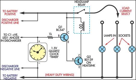
If you have a diverse assortment of 12V batteries in different conditions, this straightforward circuit will enable you to easily assess their capacity. This circuit is designed to evaluate the capacity of 12V batteries, which may be in varying...
If you've crossed the line and play guitar or bass and also sing in a band, you're almost certain to have run into the situation that you step away from the mike to do a solo (or one of...
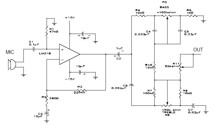
This electronic project is a simple microphone preamplifier based on the LM318 operational amplifier. The LM318 is configured as a standard non-inverting amplifier. Resistor R1 provides a ground reference for the bias current of the non-inverting input. The combination...
Warning: include(partials/cookie-banner.php): Failed to open stream: Permission denied in /var/www/html/nextgr/view-circuit.php on line 713
Warning: include(): Failed opening 'partials/cookie-banner.php' for inclusion (include_path='.:/usr/share/php') in /var/www/html/nextgr/view-circuit.php on line 713