
usb pow
The USB POW circuit is designed to address the limitations imposed by the USB standard regarding current supply and voltage stability. It incorporates features to manage inrush current, thus preventing excessive current draw during the startup phase of connected devices. This is particularly important for devices such as external hard drives, which may require a surge of current to initiate their operation.
The PCB layout is optimized for minimal resistance and inductance, which helps mitigate voltage drops across long cable runs. The use of quality components, including low-resistance traces and suitable capacitors, ensures that voltage levels remain stable, even under high load conditions. The design also includes protection mechanisms to safeguard both the USB devices and the host controller from potential damage due to overcurrent situations.
USB POW’s compatibility with various DC power supply configurations enhances its versatility, allowing it to be integrated into different systems without the need for extensive modifications. This adaptability makes it suitable for use in a range of applications, from consumer electronics to industrial equipment. The detailed schematics provided for revision 1.3 highlight the circuit's functionality and layout, serving as a guide for implementation and troubleshooting.
In summary, USB POW is a robust solution for ensuring reliable operation of high-power USB devices, particularly in scenarios where host controllers may be inadequate in providing the necessary power. The thoughtful design and engineering principles employed in the USB POW circuit make it an essential component for enhancing USB device performance and reliability in various applications.The USB standard restricts the current consumption of all USB devices to either 100mA or 500mA depending on the specifics of the USB hub and/or host controller (i. e. computer) that is supplying the power. Ideally, no USB device should ever pull more than 500mA of current from a USB port. In reality this is not always the case. There are two main issues that can cause a USB device to attempt to exceed the 100mA or 500mA limit. The first is high "inrush" current during the startup of some USB devices. For example, a USB hard drive trying to spin up can temporarily attempt to pull much more than 500mA from its USB port. The second issue is the connection of high-power USB devices through long USB cables or active USB "repeaters" (really really long USB cables.
) In both cases, the large voltage drop that can occur over the length of such USB cables will cause some USB devices to be under-powered and fail to work reliably. or at all. Lastly, some USB host controllers are notorious for being "weak" and unable to provide the full power required by the USB standard.
Weak host controllers are found in some laptops and peripherals with integrated USB hubs (such as computer monitors, printers, etc. ) USB POW is also ideal for allowing high-powered USB devices to work reliably with under-powered host controllers and hubs.
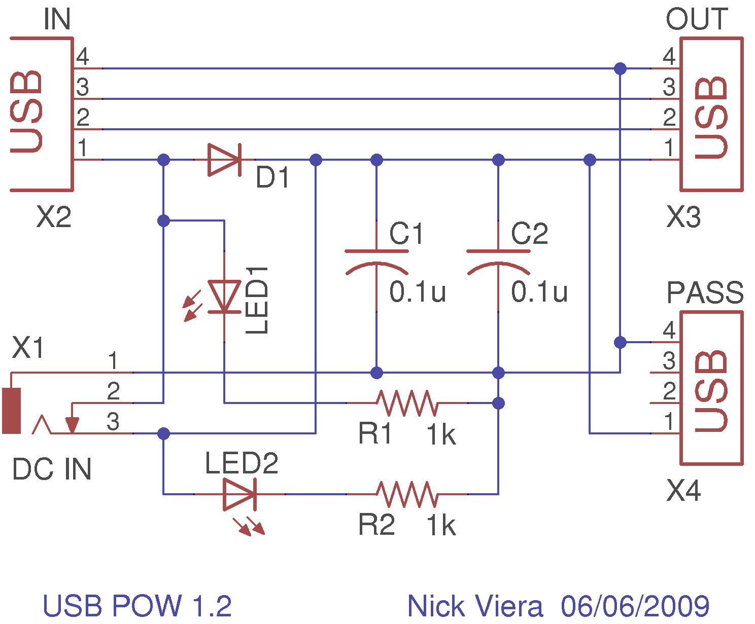
Below are the schematics for USB POW. The latest schematic is revision 1. 3. Older schematics are also shown, but only for historical information. They are not guaranteed to work correctly. The printed circuit board for USB POW is a standard 2-layer board. Board revision 1. 3 allows USB POW to be used with DC power supplies whose polarity is tip = positive, ring = negative. Board revision relies on the less common polarity tip = negative, ring = positive for proper operation.
Use the following links to: 🔗 External reference
Related Circuits
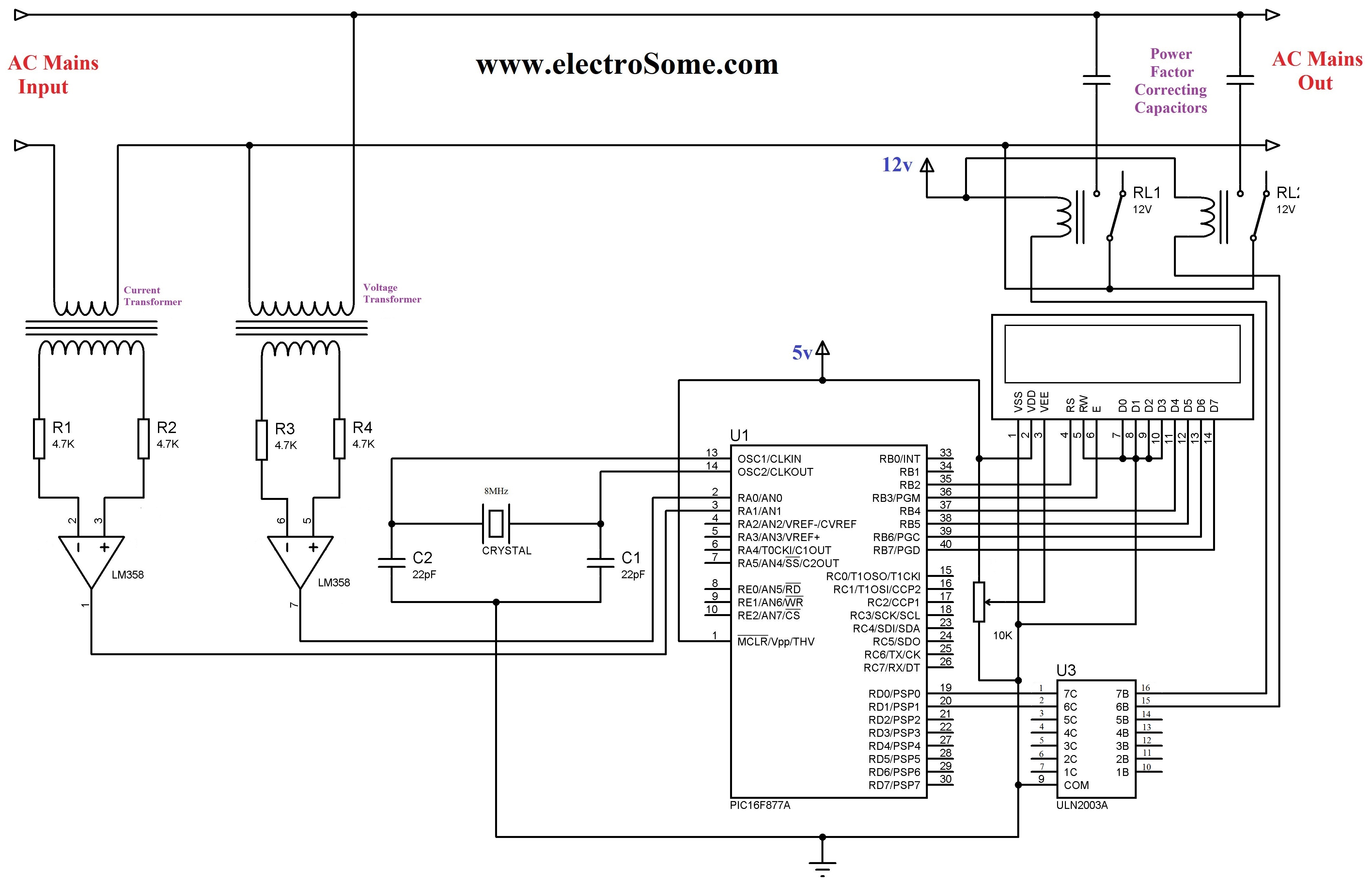
The 230 V, 50 Hz supply is stepped down using a voltage transformer, while a current transformer is utilized to extract the current waveforms. The output of the voltage transformer corresponds to the voltage across the load, and the...
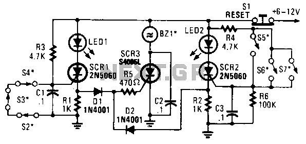
In this circuit, a low-powered silicon-controlled rectifier (SCR) is utilized to trigger a higher-powered SCR. When a switch is opened (S2, S3, S4) or closed (S5, S6, S7), either SCR1 or SCR2 is activated. This action subsequently triggers SCR3...

A reliable full bridge driver is essential for driving a flyback transformer. While many flyback driver schematics exist, most lack durability. The well-known Zero Voltage Switching (ZVS) driver, invented by Vladmiro Mazilli, is recognized for its reliability due to...

This project is a versatile power supply designed for use in electronics, capable of addressing various supply issues encountered in typical electronics workshops. It offers a continuously variable output voltage range from 3 V to 30 V, with a...
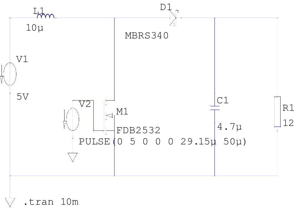
The supply voltage is 5V, and the goal is to increase it to 12V with a load current of 1A, resulting in an output power of 12W. A switching frequency of 20kHz has been selected, requiring a duty cycle...
The charger in this project is designed to charge two AA NiMH or NiCd cells of any capacity (as long as they are the same) at approximately 470mA. It will charge 700mAh NiCd cells in about 1.5 hours, 1500mAh...
Warning: include(partials/cookie-banner.php): Failed to open stream: Permission denied in /var/www/html/nextgr/view-circuit.php on line 713
Warning: include(): Failed opening 'partials/cookie-banner.php' for inclusion (include_path='.:/usr/share/php') in /var/www/html/nextgr/view-circuit.php on line 713