
USB powered device with multiple Decoupling Capacitors
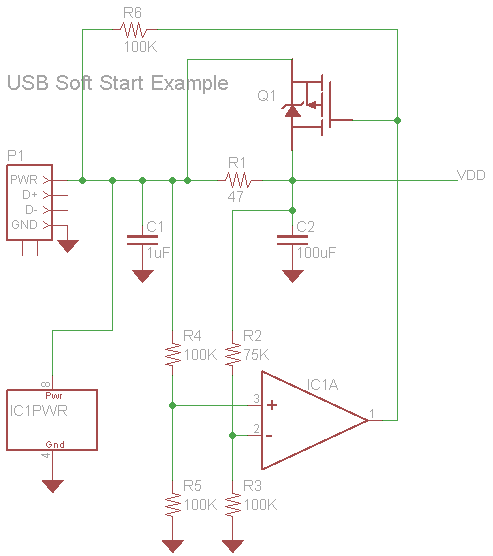
In designing a USB powered device with multiple ICs, careful consideration must be given to the decoupling strategy employed to ensure stable operation and minimize noise. Each IC typically requires decoupling capacitors to filter out high-frequency noise and provide a stable power supply. The use of a combination of capacitors, including small ceramic capacitors (e.g., 0.1µF) for high-frequency decoupling and larger electrolytic or tantalum capacitors (e.g., 2.2µF and 4.7µF) for bulk decoupling, is common practice.
To adhere to the USB specification, which limits the total decoupling capacitance to 10µF, it is crucial to analyze the configuration of these capacitors. When capacitors are connected in parallel, their capacitances add up, which can lead to exceeding the maximum allowed capacitance. Therefore, it may be beneficial to strategically place the smaller capacitors as close as possible to each IC to effectively decouple high-frequency noise, while positioning the larger capacitors slightly further away to provide bulk decoupling without exceeding the capacitance limit.
In scenarios where multiple ICs are present, it may be advantageous to group the larger decoupling capacitors of certain ICs together, thereby allowing for a shared bulk decoupling solution. This approach can help maintain compliance with the USB capacitance limit while still providing adequate power stability to each IC. Additionally, careful layout considerations, such as minimizing trace lengths and ensuring a solid ground plane, can further enhance the effectiveness of the decoupling strategy, leading to improved overall performance of the USB powered device.A USB powered device with multiple IC`s. From what I`ve read it`s standard practice to use a combination of multiple range capacitors for decoupling each individual IC, with the smallest being as close as possible and larger capacitors not too far away. According to this source, the maximum allowed decoupling capacitance for a USB device is 10uF. With several IC`s all having a combination of 0. 1uF and 2. 2uF/4. 7uF decoupling capacitors, I`m easily exceeding this limit because they`re all in parallel. The only solution I can think of is to reduce/eliminate the larger decoupling capacitor and/or try to clump a few IC`s larger decoupling capacitors together while keeping the smaller decoupling capacitors close to each IC. 🔗 External reference
Related Circuits
This document presents a schematic diagram of an electret microphone pre-amplifier utilizing the LMV721 operational amplifier. The LMV721 is chosen for its low noise and low power characteristics. The electret microphone pre-amplifier circuit is designed to amplify the weak audio...
Build an interface board to connect scientific equipment, specifically a pair of photovoltaic tubes, to a personal computer for acquiring measurement results. The signal properties include two channels with a common ground, a one-second acquisition time, and a maximum...
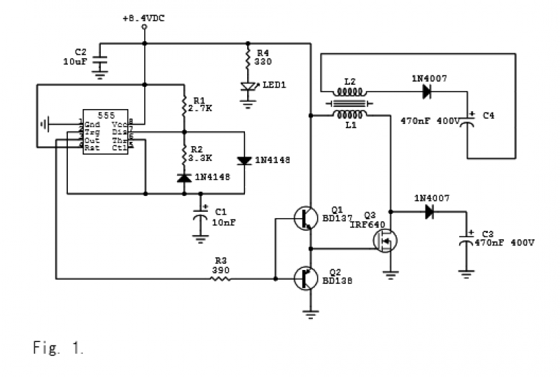
The circuit is depicted in Figures 1-2 and has been successfully tested. It is a charger based on the 555 timer integrated circuit (IC), operating at 8.4 VDC. With resistor values of R1 = 2.7 kΩ, R2 = 3.3...
The MAX5953A offers a straightforward, cost-effective, and comprehensive non-isolated power integrated circuit (IC) solution for Powered Devices (PD) in Power-over-Ethernet (PoE) systems. The MAX5953A is designed to facilitate the implementation of Power-over-Ethernet applications by providing an efficient means of...
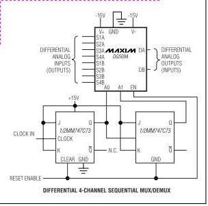
Maxim's DG508A and DG509A are monolithic CMOS analog multiplexers. The DG508A is a single 8-channel (1-of-8) multiplexer, while the DG509A is a differential 4-channel (2-of-8) multiplexer. Both devices guarantee high performance and reliability. The DG508A and DG509A analog multiplexers are...
A modified version of the previous program allows control of multiple servomotors, utilizing all available I/O lines on port B. The following listing demonstrates the control of two servos similarly to how a single servo was managed in the...