
USB-Powered PIC Programmer
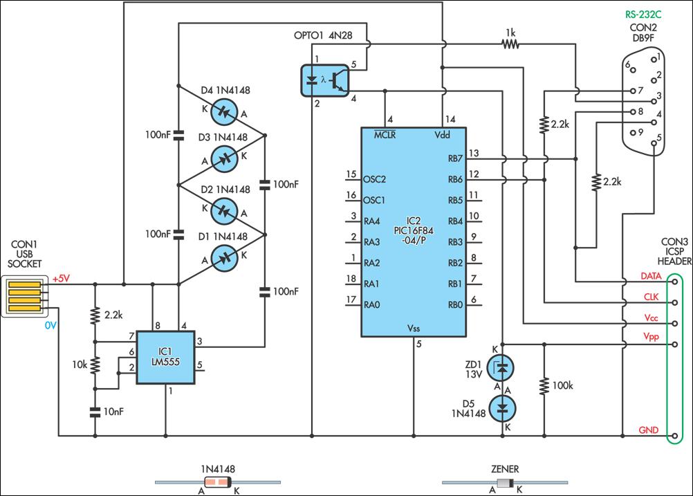
The circuit design for programming the PIC16F84 microcontroller is centered around a 555 timer IC, which serves as an oscillator to generate the necessary programming voltage. The 555 timer operates in astable mode, producing a square wave output at a frequency of approximately 6.5 kHz. This frequency is suitable for driving the subsequent components of the circuit effectively.
The output from the 555 timer is connected to a voltage multiplier stage, which consists of four 100nF capacitors and 1N4148 diodes arranged in a Cockcroft-Walton configuration. This configuration allows for the generation of a higher voltage from the 5V supply provided by a USB port. The capacitors charge and discharge in a manner that effectively steps up the voltage, making it suitable for programming the microcontroller.
During the programming process, the output from the voltage multiplier is routed to the MCLR/Vpp pin of the PIC microcontroller through a 4N28 optocoupler. The optocoupler serves to isolate the microcontroller from the timing circuit, enhancing the safety and reliability of the programming operation. When the optocoupler is activated, it allows the higher voltage from the multiplier to reach the MCLR/Vpp pin, enabling the programming mode.
To prevent damage to the microcontroller, diodes ZD1 and D5 are included in the circuit to clamp the output voltage to approximately 13.6V. This ensures that the maximum allowable input voltage (Vihh) for the PIC is not exceeded, protecting the device from potential over-voltage conditions. Additionally, a 100kΩ pull-down resistor is connected to the MCLR/Vpp pin. This resistor ensures that the pin is held at a valid logic low level (Vil) when the optocoupler is not conducting, preventing unintended programming or activation of the microcontroller.
The design is compatible with the JDM programmer standard, which is widely used for programming various microcontrollers. This compatibility allows the circuit to be integrated with software like ICProg, making it a versatile solution for programming flash memory microcontrollers in various applications.This simple circuit can be used to program the PIC16F84 and similar "flash memory" type parts. It uses a cheap 555 timer IC to generate the programming voltage from a +5V rail, allowing the circuit to be powered from a computer`s USB port. The 555 timer (IC1) is configured as a free-running oscillator, with a frequency of about 6. 5kHz. The output of the timer drives four 100nF capacitors and 1N4148 diodes wir-ed in a Cockroft-Walton voltage multiplier configuration. The output of the multiplier is switched through to the MCLR/Vpp pin of the PIC during programming via a 4N28 optocoupler.
Diodes ZD1 and D5 between the MCLR/Vpp pin and ground clamp the output of the multiplier to about 13. 6V, ensuring that the maximum input voltage (Vihh) of the PIC is not exceeded. A 100k © resistor pulls the pin down to a valid logic low level (Vil) when the optocoupler is not conducting.
The circuit is compatible with the popular "JDM" programmer, so can be used with supporting software such as "ICProg" (see ). 🔗 External reference
Related Circuits
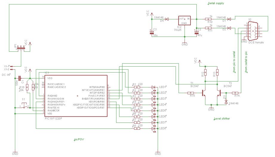
PicPOV is a project based on "persistence of vision." A PIC microcontroller blinks 8 LEDs on and off so that when waved through the air, a message is displayed. The PicPOV project utilizes the principle of persistence of vision to...

All that remains now is for the code to be compiled and converted to a HEX file that the PIC can understand. This is achieved easily with the PIC compiler that comes with the PICBASIC package. The PIC is...
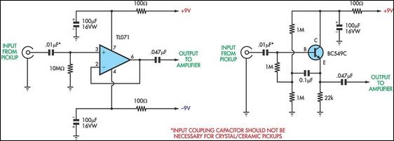
Although several variations of a standard RIAA preamplifier for magnetic phono cartridges have been published, there has not yet been a preamp stage designed specifically for ceramic cartridges. The RIAA preamplifier is an essential component in the audio signal chain,...
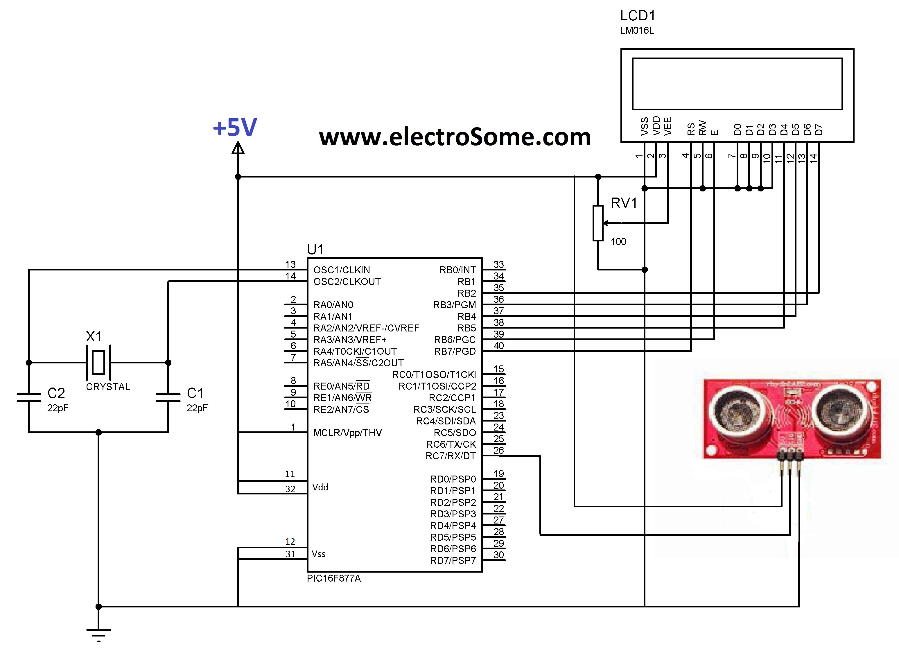
LCD initializations in 8051 C programming involve understanding the logic behind serial communication, including the duration of SIG pulse transmission and the necessary delays. These statements inform the compiler that a 16x2 LCD is connected to the defined pins...
We hold the first rights to the presentation of this approach and the best part is: It's FREE! The PIC12C508A is one of the most amazing devices but because it does not come in a low-cost re-programmable form, it...
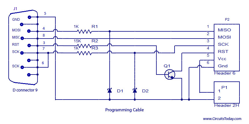
ISP programmer with circuit diagram for AVR Atmega32 microcontroller. This ISP burner circuit is an adaptation of the Pony programmer and uses PonyProg software. The ISP (In-System Programming) programmer designed for the AVR Atmega32 microcontroller allows for programming the microcontroller...