
USB selector switch
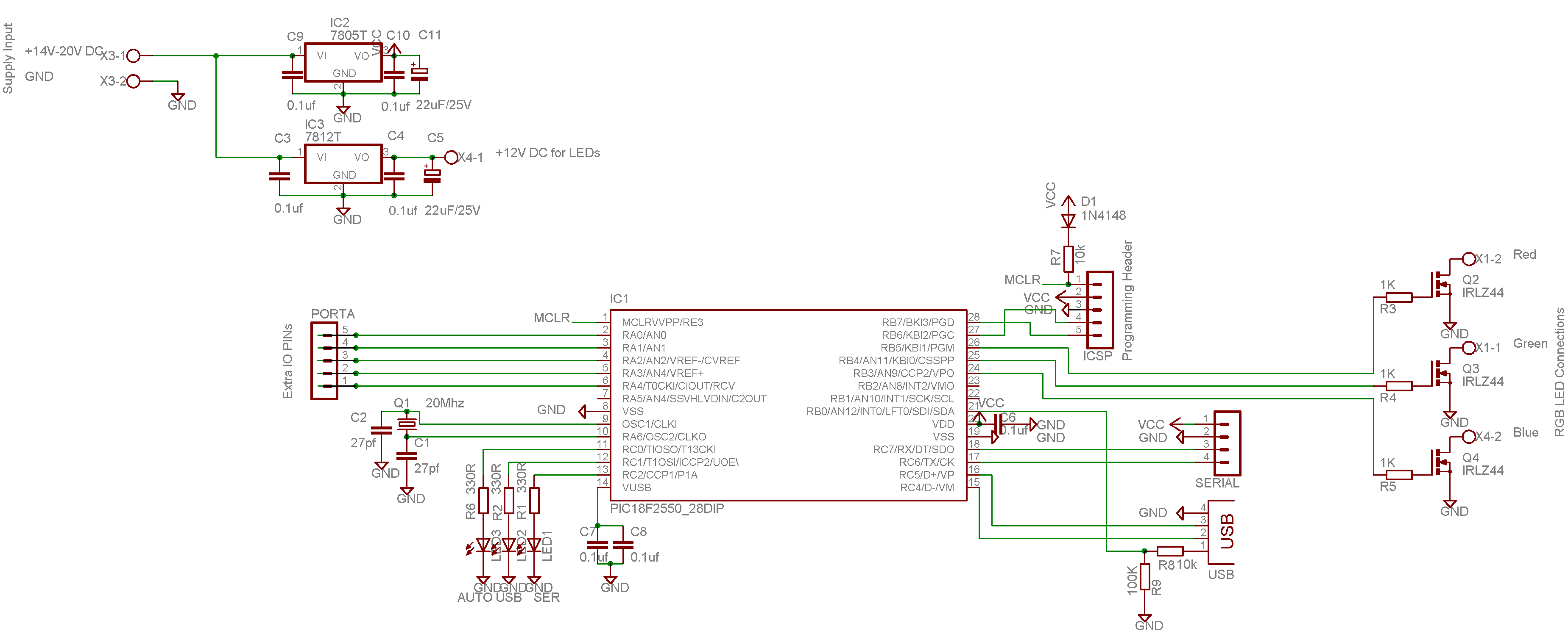
The circuit described is a USB switch that allows two computers to share a USB printer or other peripherals. The main component of this circuit is the microcontroller IC 1, which controls the switching of the printer connection between the two computers. It communicates with the computers via USB and is powered by the USB ports of both computers, providing +5 V and up to 500 mA of current.
The microcontroller operates at a reduced voltage of 3.3 V, achieved by using three diodes (1N4001) to create a voltage drop from the +5 V supply. This voltage is suitable for the low-speed USB devices, ensuring compatibility and stability. The circuit includes two relays (RE 1 and RE 2) that switch the printer connection between the two computers. The relays are operated by transistors (T1 and T2) that are controlled by the microcontroller.
The circuit also includes protective diodes to prevent reverse current that could damage the transistors. Status LEDs indicate whether each relay is engaged. The design allows only one relay to be activated at a time to minimize power consumption. Terminating resistors are included for the USB channels to ensure signal integrity.
The construction of the circuit is straightforward, as it consists of commonly available components. Care must be taken to ensure correct polarity during assembly. The microcontroller can be programmed with specific files to enable its functionality. After installation, the device will be recognized by the computers, and the appropriate drivers must be installed to allow the software to control the switching of the printer connection.To share a regional press like the USB printer, scanner etc. two computers, it is relatively easy. Just connect the two computers on a network device and say the printer as shared. This method however requires the continued operation of the computer we plugged the printer. Solution to above problem is to give the circuit that we present, and has the potential to be transferred to the printer on whichever computer we want, because the printer is connected to one of two computers, but in construction. With lower prices on laptop computers became affordable sailer acquisition and the average Greek. Getting two computers, however, automatically generated and the need to link them with the most common peripherals already available, such as a printer, a scanner, the WEB camera, the ISDN NetMod and others. To select the type of interface with computer peripheral into account that we have the most modern peripherals are interconnected USB, leading us to this choice.
As a USB peripheral to mention USB printer. The position may well be a scanner, a camera or other USB device preferably low-speed USB 1.1 (1.5 Mbps), this does not mean it can not work with devices and USB 2.0. Since we manufacture include mechanical parts, perhaps create problems in some regional communication through the floor construction, because of both high speed as this USB 2.0 (480 Mbps) and "noise" generated in the contacts of the relay.
According to the block diagram in Figure 1, the printer is connected to computer # 1 and the No. 2 microprocessor computer. When given the mandate by the software construction (USBswitch. exe), is the cross-switching devices and the printer is now No. 2 on the computer and the microcontroller to the computer # 1. The theoretical circuit The circuit consists of a few parts of the microcontroller IC 1 to take control of where it is attached printer, and is responsible for communicating with software the computer through the port USB. The supply of construction is of the USB ports of both computers and +5 v supply voltage with maximum current of 500 mA each, capable of not only the power of our workmanship but also the peripheral to be connected.
Moreover, this ensures the smooth operation of our manufacturing where we have a single computer. The data signals D + and D - the USB bus are level 0 and +3.3 V. The IC 1 but operates with TTL levels 0 and +5 V. So there are two ways to adapt: ??either to build a converter station from the 5 V at 3.3 V and back to the data bus D + and D - or down trend Power of IC 1 to 3.3 V when the signal level is between 0 and 3.3 V. The Atmel We guarantee that the operating voltage of a ATtiny 2313 is between 2.7 V and 5.5 V, so we chose the second way, namely the operation of the IC 1 to 3.3 V.
Instead of a stabilizer to 3.3 V chose three diodes 1 N 4001 (D 5 - D 7) are in the right time creates a voltage drop 0.7 V therefore, VCC = 5 - (0.7 * 3) = 2.9 V. This in theory because in practice the voltage is about 3 V. The specification of the USB bus for low-speed devices is 2.7 - 3.6 V so that 3 V enough. R 6 is the load resistance to ensure the circuit always 3 V. The relay RE 1 and RE 2 assume the IC 1 line with the first and second printer to the computer. The RE 1 working backwards from RE 2. That is reinforced when the RE 1, the RE 2 is disarmed, and vice versa. When the base of T 1 we have 0 V, the transistor will not conduct a collector and thus will We have +5 V winding through the RE 1.
The voltage of 5 V is driven at the base of T2 putting a state conductivity. By the same logic when the base of T1 will have 3 V, will pass a state conduction voltage dropping to 0 V collector and thus drive the RE 2 disarm. The diodes D 1, D 3 are used to protect the T1 and T2 of the reverse currents generated in the windings of RE 1 and RE 2.
The LEDs D 2, D 4 are indicative of the status of each relay (ON - OFF). The relays have a rated voltage of 6 V DC and consumption is a ~ 20 mA. For this reason we chose to arm only one at a time and not to arm or disarm both simultaneously, thus reducing the overall power consumption of the circuit. The R 7, R 8 is terminating resistors channel USB. Without Poles R 9 D - USB port to +3 V thus indicating the existence of low-speed device USB (1.5 Mbps).
Construction of the circuit The construction of the circuit will not be a problem because of its simplicity. Little attention should be paid to the polarity of the materials (diodes, capacitors, integrated). Glue the first shorter and smaller components and then the bigger and taller. The black lines connecting the holes in the plan of placing materials are wire bridges on top of the board.
The LEDs D 3, D 4 and resistors R 1, R 2 can not be placed on reducing the power consumption at 6 mA. If you can not find ATtiny 2313 market you in a position to schedule the same files. Hex and. eep an AT 90 S 2313 and put on the same basis as they have the same layout on the pins. If, after connecting the peripheral to the computer, show you the message that found an unknown device and you've already installed drivers will need to remove one of the diodes D 5 and D 6 and D 7 and the position of the stick a wire bridge.
With this conversion will increase the voltage VCC from 3 V at 3.7 V, sufficient for the proper functioning of the AT 90 S 2313. The AT 90 S 2313 can operate from 2.7 V - 6 V. Then what is the reason to move up the voltage to 3.7 V and can be operated with 2.7 V; The reason is simple.
The operating voltage is 2.7 V as the maximum operating frequency, which is 10 MHz. In our case, however, the operating frequency is increased to 12 MHz ie 20% more (overclocking). For this reason we can not work at lower voltage. On the other hand, ATtiny 2313 has a maximum operating frequency of 20 MHz so that we can comfortably operate at 2.7 V. Programming IC1 The microcontroller IC 1 should be programmed with two files. Flash memory you should plan to file USBswitch. hex and internal memory eeprom the file USBswitch. eep. If you do choose ATtiny 2313 against AT 90 S 2313 should range from
Crystal Osc.; Frequency 8 - MHz; Start-up time 14 CK + 65 ms; (CKSEL = 1111 SUT = 11)>. This will have to check because this microcontroller has the ability to activate the internal oscillator 0.128 - 8 MHz, and should make sure that is selected using the external crystal frequency of 8 MHz and more. Operation When connected to the construction of our one free USB port computer through the door K1, the computer will recognize a new device and ask the drivers (Drivers).
The driver for the device «USB switch »located in the folder« Driver »and consists of three files: AVR 309. dll, AVR 309. Inf and AVR 309. sys. After installing the drivers, the device is ready for use. And both computers must have installed the drivers and the program «USBswitch. Exe». When you connect both computers to our device, install drivers and run the program USBswitch. Exe, we see that the computer will see a message in Figure 3 and in another the message of Figure 4. One that will display the message in Figure 3 will be connected to the printer. In this case, as you can see the button "Connect to a common regional" is disabled because we have already connected the printer to this computer.
In the case of Figure 4, the program informs us that the device "USB switch " ie essentially the IC 1, has been found and you can press the button "Connecting with the public regional USB» that the IC 1 to change the status of relays and switches the printer on this computer. If you do not install the driver, can not run the program. 🔗 External reference
Related Circuits
Portable radios, CD players, and cassette recorders that can also be operated from mains power often do not have a mains power switch, but instead are switched on and off using a different mechanism. Portable audio devices such as radios,...
New applications for DC voltage converters, such as the LT1070, arise every day. These converters can be adapted to nearly every imaginable ratio of input and output voltages. However, all of these circuits and devices share a common shortcoming:...
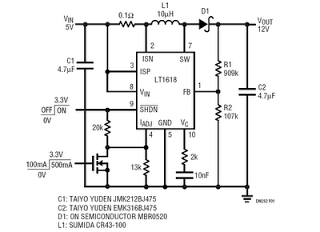
This is a 5V to 12V DC-DC step-up (boost) converter circuit designed specifically for USB-powered applications. A USB port has two current supply modes. Initially, it supplies a maximum of 100mA to the load before detecting the connected device....
This color changer mixes light from high-power LEDs to create over 16 million colors. A smooth auto-fader cycles the colors, or it can be connected to a USB port for computer control. The device utilizes a well-known color model...

Automatic Headlight Brightness Switch Circuit. Driving on the highway with high-beam headlights can significantly enhance visibility; however, it can also pose a blinding hazard for other drivers. This straightforward circuit can be integrated into your headlight system. This automatic headlight...
Any button from any remote control can be used to operate this universal switch. The button needs to be pressed for two seconds (determined by R3 and C2) before the relay activates. Once activated, the circuit remains latched in...
Warning: include(partials/cookie-banner.php): Failed to open stream: Permission denied in /var/www/html/nextgr/view-circuit.php on line 713
Warning: include(): Failed opening 'partials/cookie-banner.php' for inclusion (include_path='.:/usr/share/php') in /var/www/html/nextgr/view-circuit.php on line 713