
Infra Red Switchs
This universal switch circuit utilizes a remote control to toggle a relay, allowing for remote operation of various electrical devices. The key components include an infrared receiver (IC1), which captures modulated IR signals from the remote control. The TTL output from IC1 indicates the presence or absence of an IR signal, facilitating the activation of the circuit. The visual indicator (LED1) provides feedback to the user, confirming that the relay is being activated.
The timing circuit, consisting of the resistors and capacitors (R3, C2, R4, and D1), plays a crucial role in establishing the delay required for activation and deactivation of the relay. The charging and discharging behavior of capacitor C2, governed by resistors R3 and R4, determines the duration that the button must be pressed to engage the relay. Diode D1 ensures that the capacitor does not discharge too quickly, allowing for a stable timing mechanism.
The 555 timer (IC3) is configured in monostable mode to generate a clean, single pulse that eliminates any noise from the incoming IR signals. This pulse is essential for triggering the D-type flip-flop (IC4), which is set up as a bistable latch. The flip-flop's clock pin receives the clean pulse, and its feedback configuration ensures that the relay toggles its state with each pulse. This design effectively allows for a simple yet reliable method of controlling devices remotely.
In summary, this circuit provides a robust solution for remote control operation of electrical devices, ensuring that the relay can be activated and deactivated with a simple button press, while also providing visual feedback and maintaining stability through careful timing and signal processing.Any "button" of any remote control may be used to work this universal switch. The button must be pressed for two seconds (determined by R3 and C2) before the relay will operate. Once operated the circuit will remain in this state (latched) until reset. To reset, any button is pressed and held for the delay. For example, if you were watching TV, an d your set was tuned to Channel 3, you could press and hold the TV remote controls channel 3 button for two seconds. That way the TV viewing would not be affected and the relay would activate. You can connect anything to the relay, for example a lamp, but make sure that the relay contacts can handle the rated voltage and current.
IC1 is an Infra Red module. IR modulated pulses are received and buffered by this IC. It has a standard TTL output, the output with no signal is logic 1. One gate of a CMOS inverter and drives Red LED1 as a visible switching aid. Another gate buffers the signal and applies it to the time constant circuit, comprising R3, C2, R4 and D1. C2 charges via R3, and discharges via R4, D1 prevents quick discharge via the low output impedance of the CMOS buffer.
The pulses are further buffered and contain "jaggered edges" as shown above. These edges are produced by the modulated IR data, which has to be removed. This is achieved using IC3, a 555 timer wired as a monostable, pulse duration R5, C4. These cleanly reconstructs a single clean pulse to activate the bistable latch. A D type flip flop, IC4 is configured as a bistable. The input is applied to the clock pin, the inverted output fed back to the data input and clear and preset lines are tied to ground. For every pulse the relay will operate and latch, the next pulse will turn off the relay and so on. Note that quick turn on and off of the relay is not possible. The output pulse is set at about 1. 5 seconds and input delay by R3, C2 set at two seconds. 🔗 External reference
Related Circuits
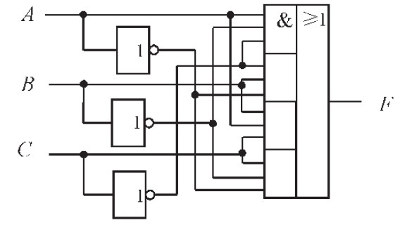
The design of the combinational logic circuit is diverse. An example chosen for detailed explanation is the implementation of an even parity check circuit. The parity check circuit exhibits particular characteristics and practicality in the analysis and design of...
Here are the schematics for infrared remotes. This remote transmits a tone using an infrared LED. This tone is decoded by the receiver. Since the receiver only switches when it "hears" the tone, there are no accidental activations. The schematic...
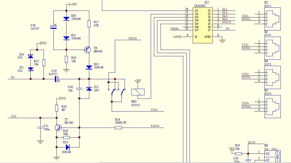
Create a simple telephone-based intercom system in a new house. Shouting between rooms is not effective, and using an instant messaging client or FaceTime lacks the immediacy of a voice call. A collection of old wired telephones is available...
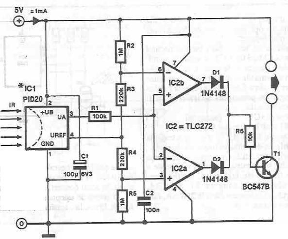
This infrared detector circuit utilizes the PID20 integrated circuit manufactured by Siemens, which converts thermal radiation into electrical impulses. It includes an operational amplifier and several electronic components. The output signal at pin 3 is compared to a reference...
This circuit is an Infra-Red Remote Control Tester designed to verify the functionality of any remote control that transmits infrared (IR) light. It operates on a 3V battery and offers several advantages, such as its compact size and the...
The DTMF infrared remote control circuit utilizes a DTMF encoded signal that can be decoded by a specialized decoder and the PLL audio decoder LM567. However, a DTMF encoded signal decoded by a single decoder yields only one frequency....
Warning: include(partials/cookie-banner.php): Failed to open stream: Permission denied in /var/www/html/nextgr/view-circuit.php on line 713
Warning: include(): Failed opening 'partials/cookie-banner.php' for inclusion (include_path='.:/usr/share/php') in /var/www/html/nextgr/view-circuit.php on line 713