
Vacuum tube tesla coil (VTTC) using Russian GI-30
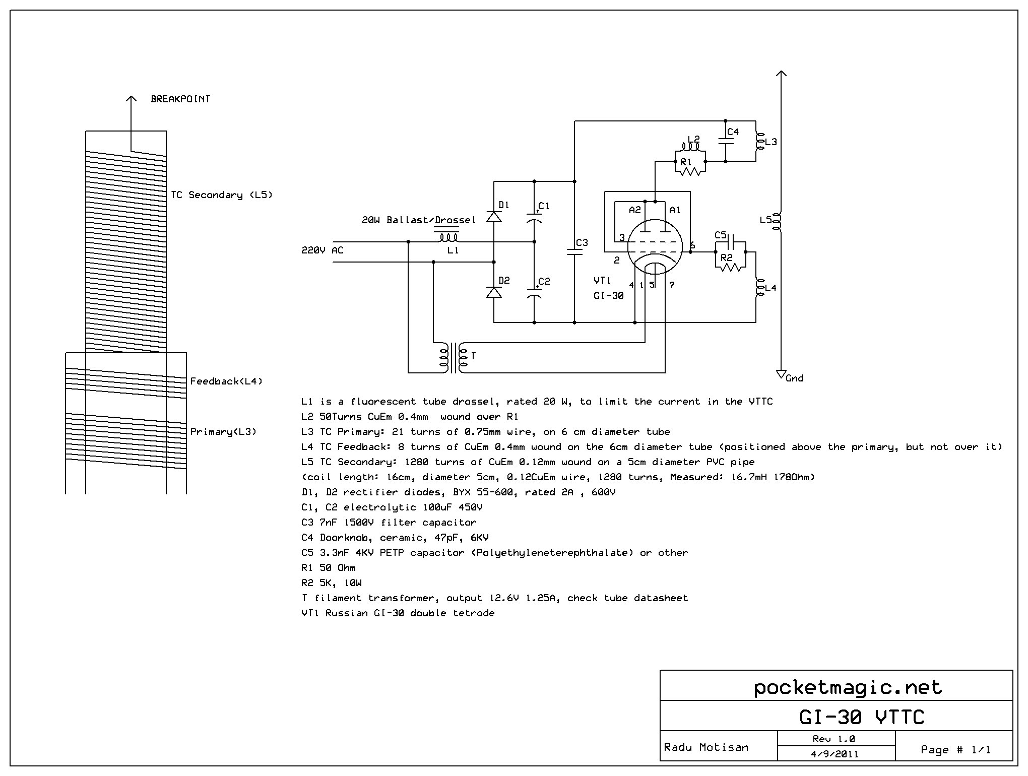
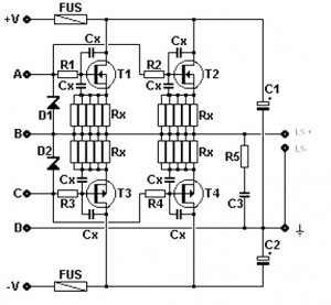
This circuit design is based on a voltage doubler configuration that converts the standard 220V AC supply into a higher DC voltage suitable for the operation of a Vacuum Tube Tesla Coil (VTTC). The voltage doubler typically consists of two diodes and two capacitors arranged in a configuration that allows the peak voltage to be effectively doubled, thus achieving the necessary 560V DC for the plate voltage.
The Armstrong oscillator circuit is characterized by its simplicity and effectiveness in generating high-voltage oscillations. The feedback coil, designated as L4, plays a critical role in sustaining oscillations by providing feedback to the circuit. The design's compactness is achieved through careful selection and arrangement of components, including a 220V ATX PC supply connector, which facilitates easy integration into the power supply system.
The system includes a dual-switch mechanism for filament voltage adjustment, allowing selection between nominal 12.6V and an under-nominal setting. This flexibility is vital for optimizing tube performance, as maintaining the correct filament voltage is crucial for the proper operation of the vacuum tube.
Experimentation with coil configurations was integral to the design process. By varying the number of turns and coil diameters, along with tuning the capacitors, the optimal conditions for spark generation and RF emissions were identified. This iterative process of testing and adjustment is essential in high-voltage applications where efficiency and performance are paramount.
The final coil design emerged as the most effective, demonstrating a balance between size and performance. The manual winding of the coil, while labor-intensive, allowed for precise control over its characteristics, ultimately leading to a successful implementation in the VTTC setup.
In the final assembly, the repositioning of electrolytic capacitors was necessary to accommodate the compact design, ensuring that all components fit harmoniously on the base. The use of additional wood to cover the capacitors not only enhances safety but also contributes to the aesthetic organization of the circuit. This careful consideration of layout and component placement is vital for achieving a reliable and efficient high-voltage circuit.A nice and compact setup, that works off-line, directly at 220V, with only a voltage doubler to get the plate voltage up to 560V DC. I don`t need to go into details explaining this circuit, it is a simple Armstrong oscillator, using the feedback coil L4.
Here is a great tutorial detailing all the basic knowledge and know-hows behind a VTTC. My goal was a compact design. I`ve used a 220V ATX PC Supply connector , a switch to power the tube, and another one to select the filament voltage (under-nominal and the nominal 12. 6V values). Careful, the voltage must be 12. 6V with the tube connected! I then tried various combination of secondaries and primaries coils, with variable number of turns or coil diameter, and adjusted the capacitors to get the best spark, RF emission, and power level.
This took some time, but it was an important step in the construction of this VTTC: It can be seen the last coil is a winner. Also it is more compact than the other 2, perfect for my setup. I had to wind it manually and this also took time, but at least I could use it successfully. For the final setup I had to move the electrolytic capacitors, and cover them with another piece of wood to make some space for the coil and oscillator and feedback caps, on the same base.
Got this nicely done: 🔗 External reference
Related Circuits
Water is a valuable resource in many regions, with numerous individuals depending on water tanks to enhance their water supply by storing collected rainwater or water drawn from a well or bore. Measuring the fullness of a tank can...
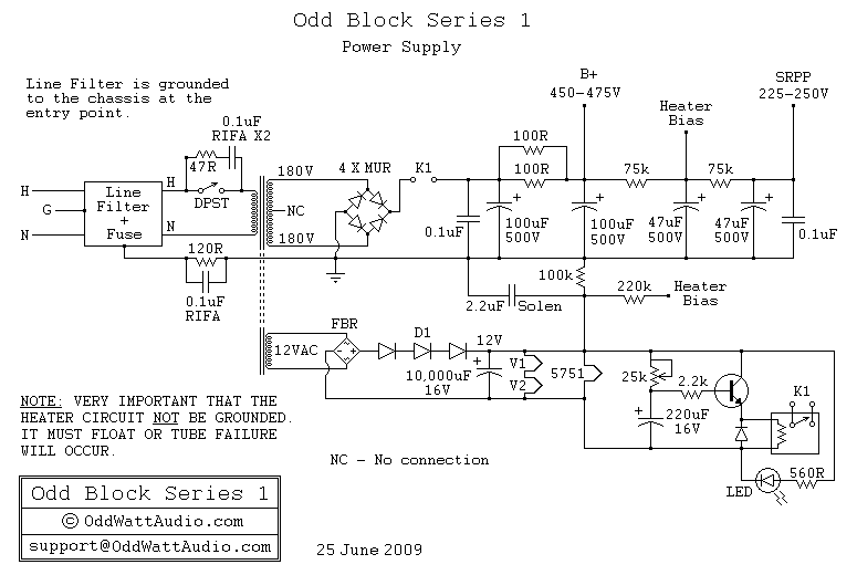
A schematic of the ability accumulation is presented below. Similar to the amplifier schematic, the ability accumulation design is © OddWatt Audio, and permission to host the schematic on this platform has been granted by OddWatt Audio. The schematic...
This circuit differs from similar circuits in view of its simplicity and a totally different concept of generating the control signals. Usually remote control circuits make use of infrared light to transmit control signals. Their use is thus limited...
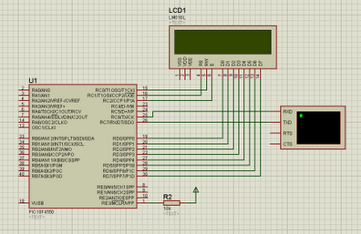
PIC18F4550 communication with a PC using USB HID class, Visual Basic communication. The PIC18F4550 microcontroller is designed to facilitate communication between embedded systems and personal computers through the USB Human Interface Device (HID) class. This microcontroller is equipped with a...
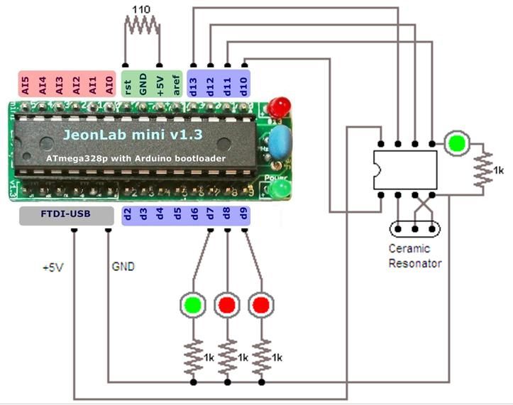
For relatively small projects with fewer pins than the ATmega328, the ATtiny series, specifically the ATtiny45 or ATtiny85, is a good choice due to its compact physical size. The ATtiny series microcontrollers, particularly the ATtiny45 and ATtiny85, are designed for...
Amplifier circuit featuring a MOSFET output stage, serving as an alternative to the output stage that utilizes bipolar transistors. Advantages of the MOSFET amplifier include ease of operation, the ability to handle hundreds of watts with straightforward parallel configurations,...