
Valves structure operation and use
A television set from the early 1950s represents a significant technological advancement, prominently featuring vacuum tubes or valves as key components. These valves are essential for controlling electric current, functioning similarly to plumbing valves that regulate water flow. In electronic terms, a valve allows for the manipulation of a stream of electrons, which necessitates a source of electrons, a target for their movement, and a mechanism to control their flow.
The schematic representation of a triode valve, as seen in historical documents, typically includes three main elements: the filament, anode, and grid. The filament serves as the electron emitter, heated to release electrons into the vacuum. The anode, connected to a high positive voltage, attracts these electrons, creating a flow of current. The grid, positioned between the filament and anode, modulates this flow. By applying a negative voltage to the grid, the flow of electrons can be reduced or entirely halted, allowing for precise control over the amplification process.
The vacuum environment within the glass envelope is critical for the operation of the valve, as it prevents electron collisions with air molecules, ensuring efficient electron flow. The base of the valve contains pins that connect to a valve holder, facilitating easy replacement when the valve fails, an inevitability given the inherent unreliability of these components.
In terms of functionality, valves act as amplifiers, capable of increasing the strength of an input signal significantly. This amplification feature is pivotal in the design of early radio receivers, where a single valve could be employed along with an aerial to capture radio waves and headphones for audio output. The accompanying tuned circuit, often comprising inductors and capacitors, allows for frequency selection, while positive feedback enhances the gain until oscillation occurs.
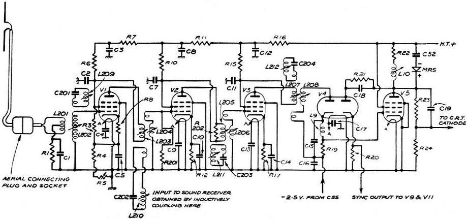
Overall, the evolution from vacuum tubes to modern semiconductor technology marks a transformative period in electronics, laying the groundwork for subsequent innovations in radio, television, and beyond. The historical context of these components highlights the ingenuity of early engineers and the foundational role of valves in the development of consumer electronics.The first television set I ever saw appeared in our house in about 1950. It looked like this - except it was in a box, obviously. My dad had built it from a kit. They made their own entertainment in those days. There was only one channel - BBC - broadcasting on 45 MHz. The programmes were rubbish, the picture was a grainy black and white on a 9" t ube, and yet my brother and I were entranced. It was the most amazing thing we had ever seen. Moving pictures! Right there in our living room! Some pedants refer to valves as `thermionic` valves, to distinguish them from the valves plumbers fit, whilst Americans know them as `vacuum tubes`. They look like oddly shaped light bulbs, or fat metal tubes. There are six of them visible in the picture. (OK, Don, seven if you count the CRT). Think of a plumber`s water valve, or a tap. It`s basically a pipe with an adjustable vane inside it. The vane can be rotated from outside the pipe between fully closed and fully open. You can control precisely how much water flows through the valve by adjusting the angle of the vane. A valve like those in the TV set works by controlling the flow of electric current. The key point is that both types of valve allow an external force to influence what`s happening inside.
These valves control electric current. A current is a stream of electrons, all flowing in the same direction. So a valve needs a source of electrons, a target for them to aim at, and a force to move them. Plus, of course, a means of controlling how many electrons are moving. Engineers needed a way of thinking about a valve without worrying about unnecessary details such as its physical size or the actual shape of its components. They came up with a descriptive symbol. I found this version in the March 1923 edition of Modern Wireless, and it`s still recognisably a triode.
At the bottom of the diagram is the filament. Its job is to emit electrons. At the top is the anode (or plate, as Americans say). It is connected to a large positive voltage, so the electrons swarm towards it. Between the filament and the anode is the grid. It is not solid - the electrons can pass right though it. But when a negative voltage is applied to the grid (that is, when the grid is made more negative than the filament) some electrons become discouraged on their journey, and turn back. A sufficiently large negative voltage stops all the electrons from passing whilst a zero voltage allows them all to pass unhindered.
Allowing the grid to become more positive than the cathode is generally considered a bad thing to do. It`s essential that the electrons can move freely, so the whole structure operates in a vacuum, held usually inside a glass bottle.
The base carries pins which plug into a valve-holder, allowing the valve to be replaced when it fails. And it will fail, just as a lightbulb will fail. Valves are not reliable components. A valve is an amplifier. Its output signal is much bigger than its input signal. So in principle a simple radio receiver could be made from a single valve with an aerial connected to its input and a set of headphones at its output.
Modern Wireless (July 1923) shows how. The tuned circuit (L1, C1) selects the frequency. L2 provides positive feedback - they called it "reaction" then - which increases gain and selectivity right up to the point when the circuit begins to oscillate and becomes a transmitter. In the accompanying list of Materials and Components Required, it says simply "1 valve". There is no further clue as to what type of valve is needed here, so I assume there was only one type of valve available.
The world had not yet realised what a fantastic transformation these and their successor devices (transistors and integrated circuits) would bring within a couple of generations. In the 1920s, valves existed mainly so that serious experimenters could build radio receivers. Thirty years later the serious experimenter could 🔗 External reference
Related Circuits
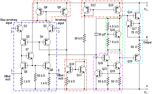
An operational amplifier, commonly referred to as an op-amp, is a DC-coupled high-gain electronic voltage amplifier featuring a differential input and typically a single-ended output. An op-amp generates an output voltage that is often millions of times larger than...
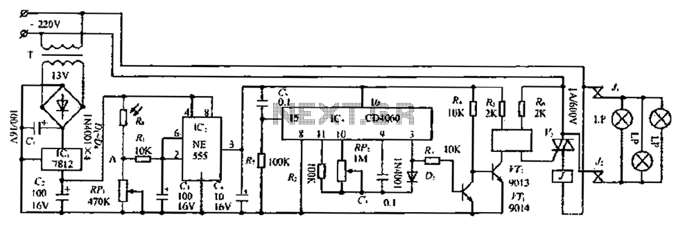
The circuit consists of three parts: a light control section, a time control section, and a power supply section. The light control section utilizes a photoresistor (Rg) and a variable resistor (RP) to detect light levels. During the day,...
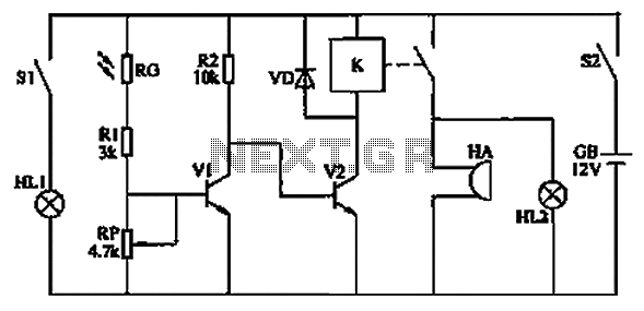
The circuit functions as a reminder system utilizing a photodetector amplifier circuit along with a sound and light alarm circuit, as illustrated in Figure 1. The photodetector amplifier circuit consists of a pilot light (HL1), a light switch (S1),...
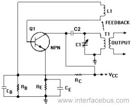
An Armstrong Oscillator is a type of oscillator that utilizes a tickler coil to provide feedback from the tank circuit. This oscillator generates a sine-wave output with constant amplitude and fairly constant frequency within the RF range. Inductor L1...
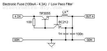
This is adjustable electronic fuse that can be used to protect power supplies from short circuits or can be also used to limit the current usage. It can be adjusted for currents from 100mA up to 4.3A. An adjustable electronic...

The voltage-to-frequency converter (VFC) in this circuit produces a satisfactory sine-shaped output; however, it lacks good voltage-to-frequency linearity and exhibits a frequency stability of approximately 0.2%. The LM331 is an excellent choice for a linear and stable voltage-to-frequency converter,...