
transistors Mystery circuit: latching relay control with transitor / capacitor why doesnt it work

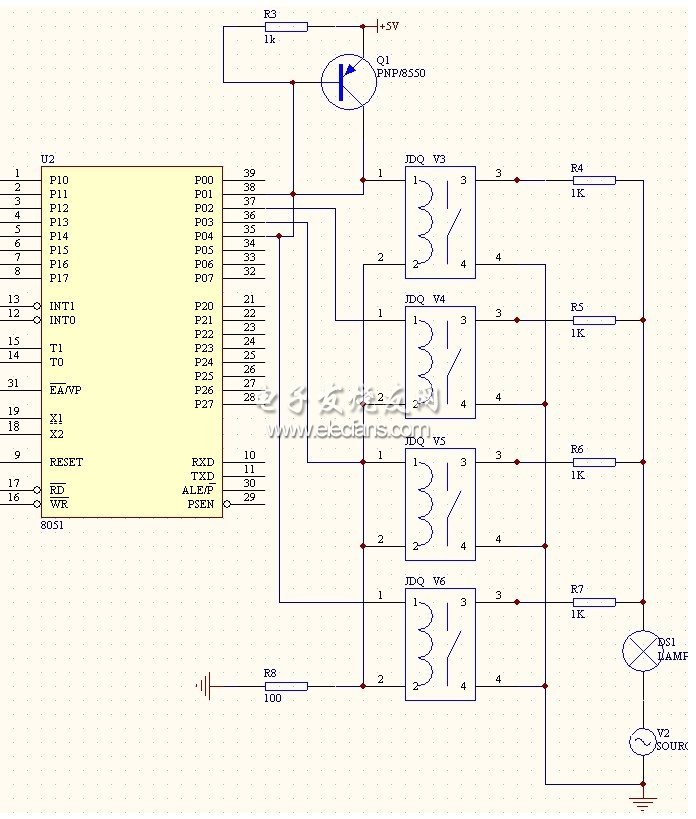
The described circuit employs a single-coil latching relay that operates by utilizing opposite polarities to latch and reset its state. This configuration allows for the control of the relay without the need for a separate coil for each state, enhancing efficiency and reducing component count.
In this setup, the transistor Q1 serves as a switch that controls the charging and discharging of capacitor C1. When Q1 is turned on, it completes the circuit, allowing C1 to discharge through the relay coil, energizing the relay and causing it to latch in an "on" position. This action is critical for applications that require persistent states without continuous power consumption.
The testing phase involved the use of dual opposite-biased LEDs connected in parallel to the relay output. The absence of flickering in either direction suggests that the relay is functioning correctly and that the circuit maintains a stable state during operation. This is an important characteristic for circuits that require reliable visual indicators.
However, the circuit's design raises potential issues. When Q1 is turned off, the relay coil's lower terminal becomes floating, which can lead to unpredictable behavior. Since C1 is in series with the relay coil, it cannot charge effectively when the path is interrupted. This could result in the relay not returning to its initial state as expected, which may lead to malfunctions in applications relying on the relay's switching capabilities.
To mitigate this issue, it may be beneficial to implement a discharge path for C1 when Q1 is off, ensuring that the capacitor can reset properly. Additionally, incorporating a pull-down resistor or a secondary discharge mechanism could provide a more reliable operation of the relay, enhancing the overall circuit performance.Using a single-coil latching relay, which latches/resets with opposite polarities. I`ve tested the circuit with dual opposite-biased LEDs too, no light flicker in either direction to indicate a charge/discharge. QuadrupleA Apr 14 `13 at 23:14 Unless there`s something missing from the circuit and/or description, I don`t see how this circuit could work.
When Q1 is on, there is a path through which C1 can discharge through the relay coil. However, when Q1 is off, the lower end of the relay coil is floating. Since C1 is in series with the relay coil, there is no path for current to charge C1. Alfred Centauri Apr 15 `13 at 0:40 🔗 External reference
Related Circuits
This circuit is designed to serve as a programmable LED display for various applications. It features an 8 x 32 LED dot matrix interfaced with a Xino (or Arduino). In addition to the display, the circuit includes two buttons...
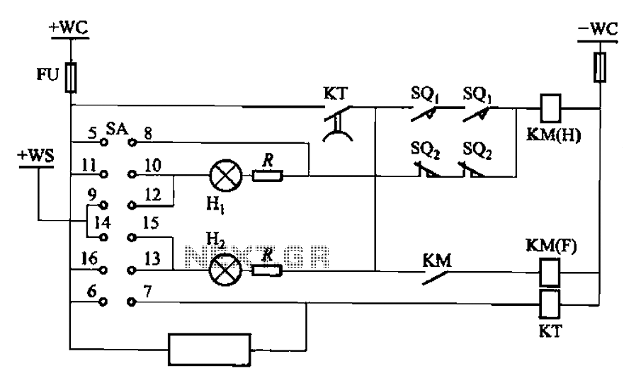
The BT9404 is a de-excitation type switch utilized with CJ4-S contactors and JT3-21/3-type electromagnetic relays. The control circuit is depicted in Figure 7-55. The KM contactors used are CJ4-S, while the time relay is the JT3-21/3. The SA component...
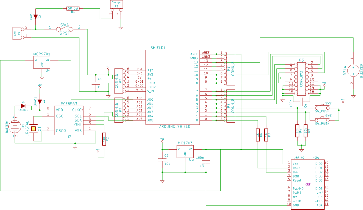
This system is a control system based on a single-chip computer that allows for remote operation of lighting. The scheme primarily addresses the transmission and reception of signals, as well as program manipulation of various signals once they are...
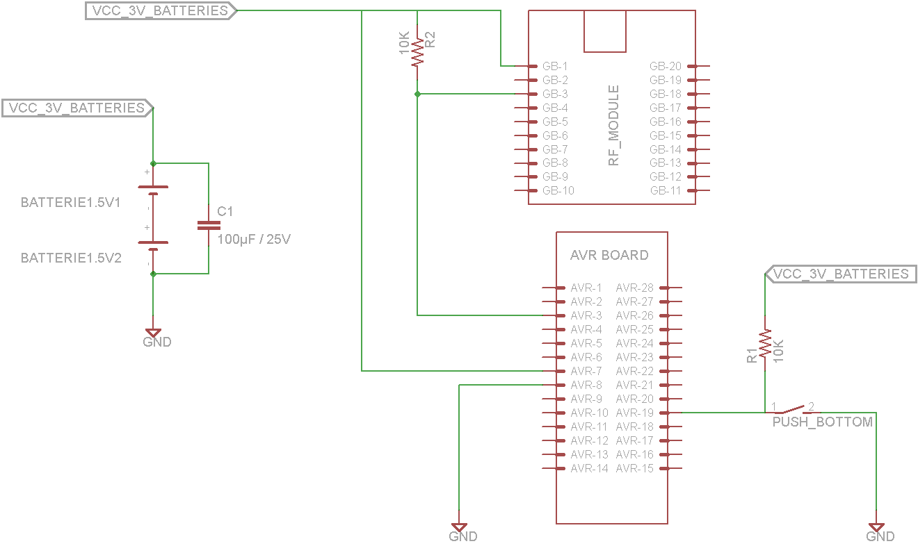
This tutorial demonstrates concepts for creating a lamp with dual actuation. The lamp can be controlled through a parallel switch or by a relay that is managed using an RF module based on the ZigBee protocol (IEEE 802.15.4). The...
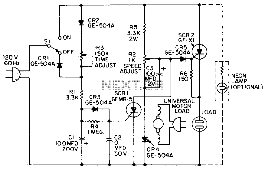
When the time delay expires, SCR1 conducts and removes the gate signal from SCR2, which stops the motor. Both the time delay and motor speed are adjustable by potentiometers R2 and R3. If heavier motor loads are anticipated, use...
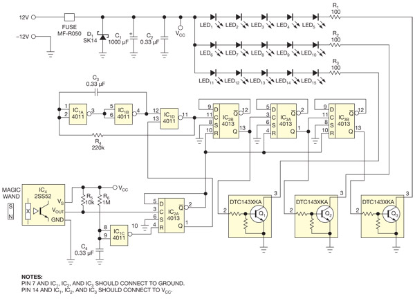
This circuit enables the activation of holiday bulbs with a wave of a magic wand. The strings of lights flash in a sequential manner. The core concept relies on a magnet. The circuit operates by utilizing a magnet as the...