
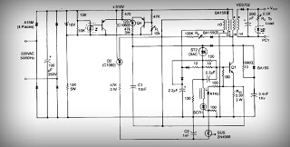
Variable current source 100ma-2amp
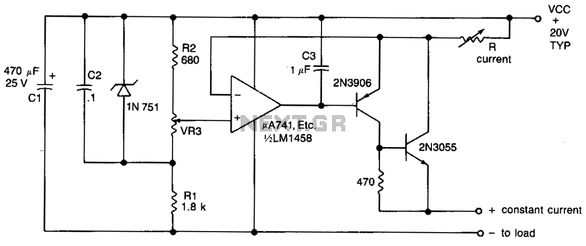
The described circuit utilizes a transistor-based current regulator configuration, where the output current is primarily controlled by the resistor R in the collector of transistor Tr2. The ability to vary this resistor allows for a flexible output current range, which is essential in applications requiring precise current regulation. The variable resistor VR3 plays a crucial role in fine-tuning the reference voltage supplied to the non-inverting input of the operational amplifier (op-amp).
The operational amplifier is configured in a feedback arrangement, where the output is connected back to the inverting input. This feedback mechanism is vital for maintaining the desired current output. The voltage across resistor R is kept constant, equal to (VCC - VIN), where VCC represents the supply voltage and VIN is the input voltage. This constant voltage across R ensures that the current flowing through the load remains stable, regardless of variations in load resistance or supply voltage fluctuations.
In practical applications, this circuit can be employed in power supply systems, LED drivers, or any scenario where a stable and adjustable current is necessary. The ability to set the output current between 100 mA and 2 A with fine control allows for versatility in various electronic applications, making it a valuable design in modern electronics.The output current is set by the resistor R in the collector of Tr2, which may be varied to offer a range of output currents from 100 mA to 2 A with fine control by means of VR3 which varies the reference voltage to the non-inverting input of the op amp. The feedback path from the output to the inverting input of the op amp maintains a constant voltage across R, equal to (VCC-VIN) and hence a constant current to the load given 🔗 External reference
Related Circuits
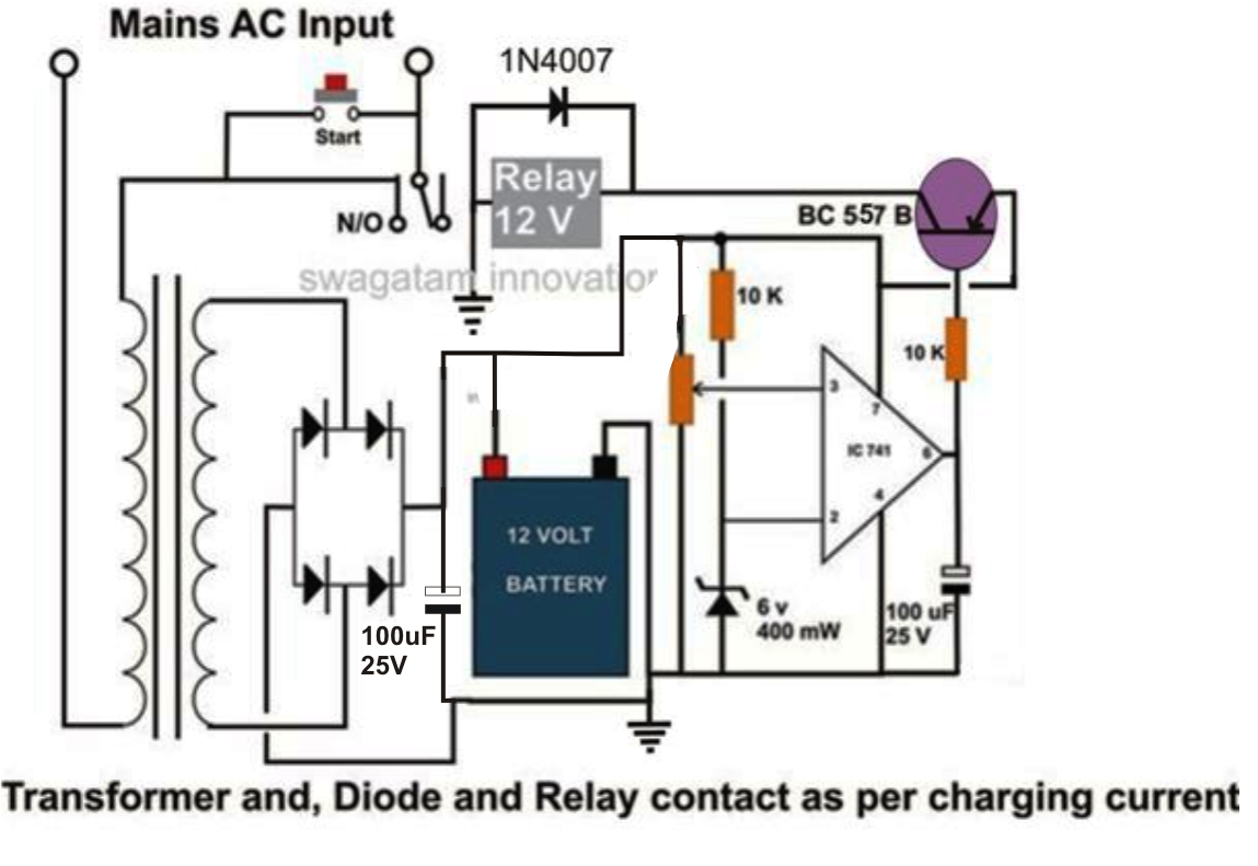
This design is intended for charging high-capacity lead-acid batteries in the range of 100 to 200 Ah. The system operates automatically, disconnecting power from both the battery and itself once the battery is fully charged. For simplicity, a filter...
The BQ2000 is a programmable, monolithic integrated circuit designed for fast-charge management of nickel cadmium (NiCd), nickel metal-hydride (NiMH), or lithium-ion (Li-Ion) batteries in single or multi-chemistry applications. The BQ2000 detects the battery chemistry and employs optimal charging and...
In this circuit, an LM339 quad voltage comparator is utilized to generate a time delay and control a high current output at low voltage. Approximately 5 amps of current can be sourced using a pair of fresh alkaline D...
The circuit begins with a step-down mains transformer featuring a secondary winding rated at 24 V/3 A, which connects across the input points at pins 1 and 2. The quality of the output supply is directly related to the...
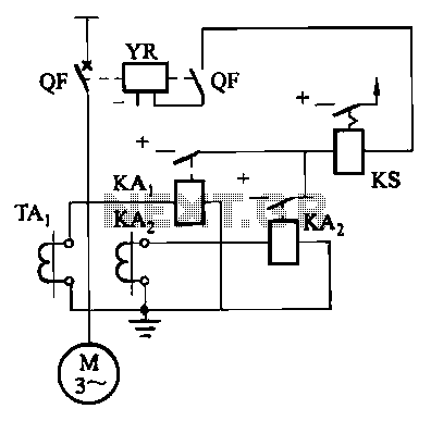
Figure 4-52 (a) illustrates the two-phase wiring for direct current (DC) operation, while Figure 4-52 (b) depicts the two-phase current differential wiring for alternating current (AC) operation. The schematic in Figure 4-52 (a) represents a two-phase wiring configuration suitable for...
This is a low voltage, high-current output switching DC power supply with an input of 220 volts AC. In this circuit, an ST2 DIAC relaxation oscillator, Q3, C1, and the DIAC initiate conduction of the output switching transistor Q1....