
vary Precise Lc Meter

The schematic has been designed without the use of reed relays, which can be difficult for hobbyists to source locally. Instead, a MOSFET was initially considered, but the best results were achieved using a standard NPN transistor, such as the BC547. Users who prefer reed relays can incorporate them into the design. The internal comparator of the PIC is utilized for the oscillator, which is connected to Timer1 as an external clock source for frequency calculation, thus eliminating the need for an external LM311 operational amplifier. A relay (RL1) is employed to switch between L and C measurement modes.
The meter's operation is based on four fundamental equations. For measuring both unknown L and C, two common equations are used. The first frequency (F1) is determined with the internal LC tank circuit, followed by connecting a calibration capacitor (Ccal) in parallel with the tank circuit to obtain a second frequency (F2). The raw values of inductance or capacitance are then automatically scaled to engineering units and displayed on a 16x2 LCD. For those unfamiliar with the mathematics, it is advisable to focus on building the hardware first and follow the calibration process outlined in the subsequent section.
Precision is influenced by the quality of components used. The two 33pF capacitors in the oscillator should be tantalum to minimize series resistance and inductance. Capacitors C4 and C5 (Ccal) should be of the polystyrene type, as green capacitors can exhibit significant value drift. Ceramic capacitors are to be avoided due to potential high losses. After assembling the circuit, short two test LEDs and power the device, allowing it to auto-calibrate. The default mode is set to measure inductance. After a warm-up period of several minutes, pressing the "zero" button prompts a recalibration, and the display should read 0.00 µH.
Next, connect a known value inductor, such as 10µH or 100µH, to verify that the LC meter reads close to the actual value, with an acceptable error margin of up to ±10%. To fine-tune the meter for a closer accuracy of ±1%, refer to the schematic for jumpers JP1 to JP4. JP1 and JP2 are used to adjust the value upwards or downwards, respectively, by connecting them and executing the calibration process. If further adjustment is needed, JP3 can be connected to display the value of F1, which should be approximately 503292 with a 100µH inductor and a 1nF capacitor. Connecting JP4 will display F2; if no output is observed, this indicates a malfunction of the oscillator, necessitating a review of the PCB connections.Well this is a Very Accurate LC Meter based on PIC 16F628A. Having inspired from surprisingly accurate LC Meter. This is my attempt to build an accurate L/C meter. This design is little different from other designs found on the internet. The goal of my hard work is to people get success in a single try. Cz Most of the design doesn`t work as described in the documentation or lack of information`s. The most challenging part of the project was to program the entire floating point math in 2k code memory of 16F628A. Basically LC meter is a kind of frequency meter, there is an LC Tank oscillator that oscillates with measured L or C and result is being calculated.
The precision of frequency is up to 1Hz. For more details of measuring frequency with timers, see my article frequency counter. Theory of operation: Look at the schematic carefully; I didn`t use any reed relay, which is the burden for most of hobbyist, because of unavailability in local market. In my country (Bangladesh) it is also not available. So first I decided to use a Mosfet instead of Reed Relay. But I found better result in normal NPN transistor like BC547. If you don`t trust transistors, you can add Reed Relay yourself. I have used Pic`s internal comparator for oscillator and fed it to Timer1 External clock source to calculate frequency.
So it eliminates the external Lm311 Op amp. The relay RL1 used for selecting L and C mode. The meter works on four basic equations. This are For both unknown L and C, Equation 1 and 2 are Common. Means we get F1 with internal LC tank circuit then connect Ccal Parallel with tank circuit and take the value of F2. After getting the raw value of inductance or capacitance, program automatically scales the value to engineering unites.
Then shows it to 16x2 LCD with unites. If it is hard to understand all the maths better leave for a while and try to make the hardware first and go through the calibration process I referred in next section. Precision depends on the status of your components. The two 33pf capacitors in the oscillator should be tantalum (for low series resistance/inductance). Use C4, C5 (Ccal) Polystyrene type. Because Green caps tend to drift in value too much. Avoid ceramic capacitors. Some of these can have high losses (and it is hard to tell). Keep short two test leds and switch on the circuit. It will then auto calibrate. And default mode is inductance. Allow several minutes "warm-up", then press the "zero" button to force a re-calibration. The display should now show ind = 0. 00 uH Now Open two test leds and connect a well known value of inductor like 10uH or 100uH. The LC meter should read somewhere near its value (with up to +/- 10% error). Now you need to tune the meter to show the result near +/- 1%. To do so check the schematic there is 4 jumpers Jp1 ~ Jp4. Jp1 and Jp2 are delivered to + and the value. To increase the value first join Jp1 and run the process 1, 2. And to decrease the value Join Jp2 and run the process 1, 2. If you still not get the perfect value, join the Jp3 to see the Value of F1. It will show near about 503292 with 100uH L and 1nF capacitor. Or join Jp4 to see F2. If doesn`t shows anything that means your oscillator is not working perfectly. Check your PCB again. 🔗 External reference
Related Circuits
Measuring inductance is important for creating hand-made inductors, particularly when engaging in do-it-yourself (DIY) coil winding. An inductance meter adapter can facilitate this process. An inductance meter adapter is a vital tool for accurately measuring the inductance of coils and...
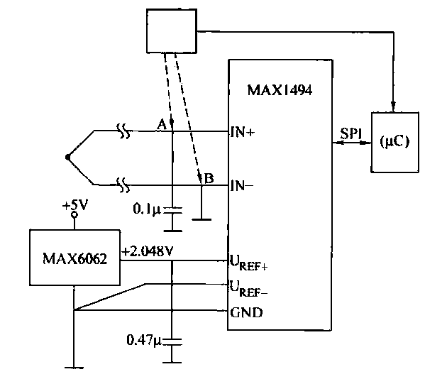
The circuit consists of the MAX1494 and a thermocouple temperature measurement system. The MAX1494 is terminated at 1N GND 5-32. An external temperature sensor, such as the DS75, can be utilized for junction temperature compensation. The MAX1494 employs an...
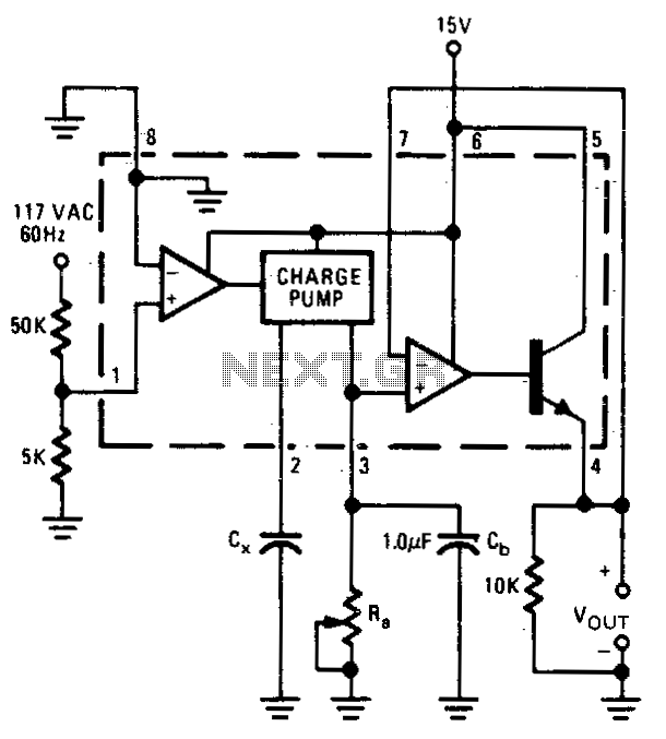
The output voltage is proportional to the capacitance connected to pin 2 of the charge pump. The meter operates over a capacitance range of 0.1 to 0 µF with a set resistance of 111 kΩ. Within this capacitance range,...
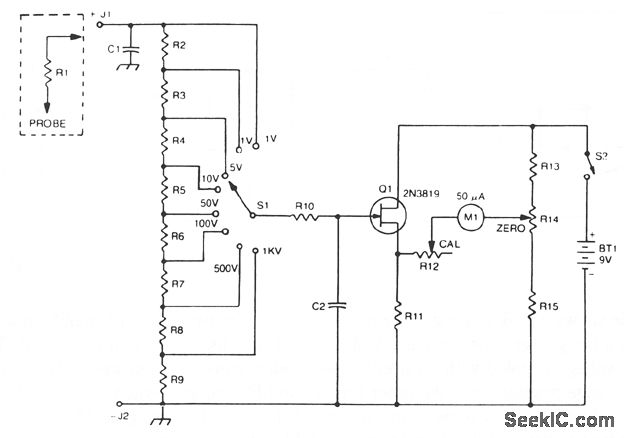
The 2N3819 FET serves as a solid-state voltage output meter (VOM). In this configuration, the 2N3819 functions as a cathode follower. The bias offset, or meter null, is achieved using resistors R14 and R12, while the full-scale calibration is...
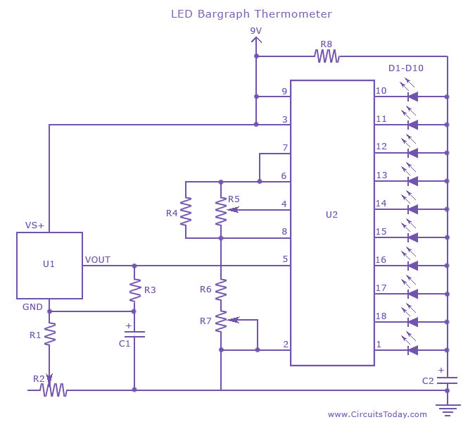
An LED thermometer that can function as a temperature sensor or temperature measurement circuit, utilizing the LM34 for Fahrenheit display or the LM35 for degree Celsius display. The LED thermometer circuit is designed to provide accurate temperature readings using either...
This LED thermometer is designed for home use, capable of reading temperatures between approximately 60 and 78 degrees Fahrenheit. It utilizes a precision temperature sensor IC, the LM34DZ, which requires no calibration and can measure temperatures ranging from -50°F...