
Vga to tv Converter
The described circuit involves the integration of a SCART interface for video output, allowing connectivity between a PC and a monitor. The first schematic serves as a simplified version of the overall design, focusing on essential connections while referencing the second schematic for detailed pin configurations.
The SCART connector is a 21-pin interface widely used in Europe for connecting audio-visual equipment. In this project, special attention must be given to the pinout configuration, specifically pins 19 and 20, which are responsible for the switching of signals. If these pins are incorrectly wired, the circuit will fail to function properly, highlighting the importance of meticulous connection checks.
The circuit design enables the user to display various media types, such as games, photos, and videos, on a monitor. However, it is noted that using Windows may result in image flickering, which could hinder text readability. This flickering issue may be attributed to the graphics output settings or incompatibility between the PC's video output and the SCART interface.
Incorporating the circuit into a monitor case allows for a compact and integrated solution. The utilization of a SCART outlet facilitates easy connection to compatible displays. Proper grounding and shielding should be considered to minimize interference and ensure stable signal integrity.
Overall, the project provides an innovative way to repurpose a PC for multimedia output through a SCART connection, with specific wiring precautions necessary for successful operation.I realized the first schematic shown here, cause it`s more simply, but I took all informations about the other pins from the second schematic, click the buttons on top and you will understand what I mean. BE careful to all connections and control everything more than once to ensure the circuit to work . Note that the scart cable must have the 19 and 20 pin inverted if it`s not so do it ! or your circuit will never work. I have put all in my monitor case and got out with a scart outlet . With this project you can play games, watch photos or video on your pc but FORGET TO USE WINDOWS, infact there is a flickering on the image that is really impossible to read texts withou 🔗 External reference
Related Circuits
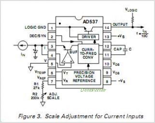
The AD650 is a voltage-to-frequency (V/F) and frequency-to-voltage (F/V) converter that offers high-frequency operation and low nonlinearity, features that were previously unavailable in a monolithic form. Its inherent monotonicity in the V/F transfer function makes the AD650 suitable for...
I made the power supply which makes about +30V with +5V power supply. The direct current is changed into the alternating current by the oscillator which used the schmitt trigger inverter which has the hysteresis characteristic and the resonance...
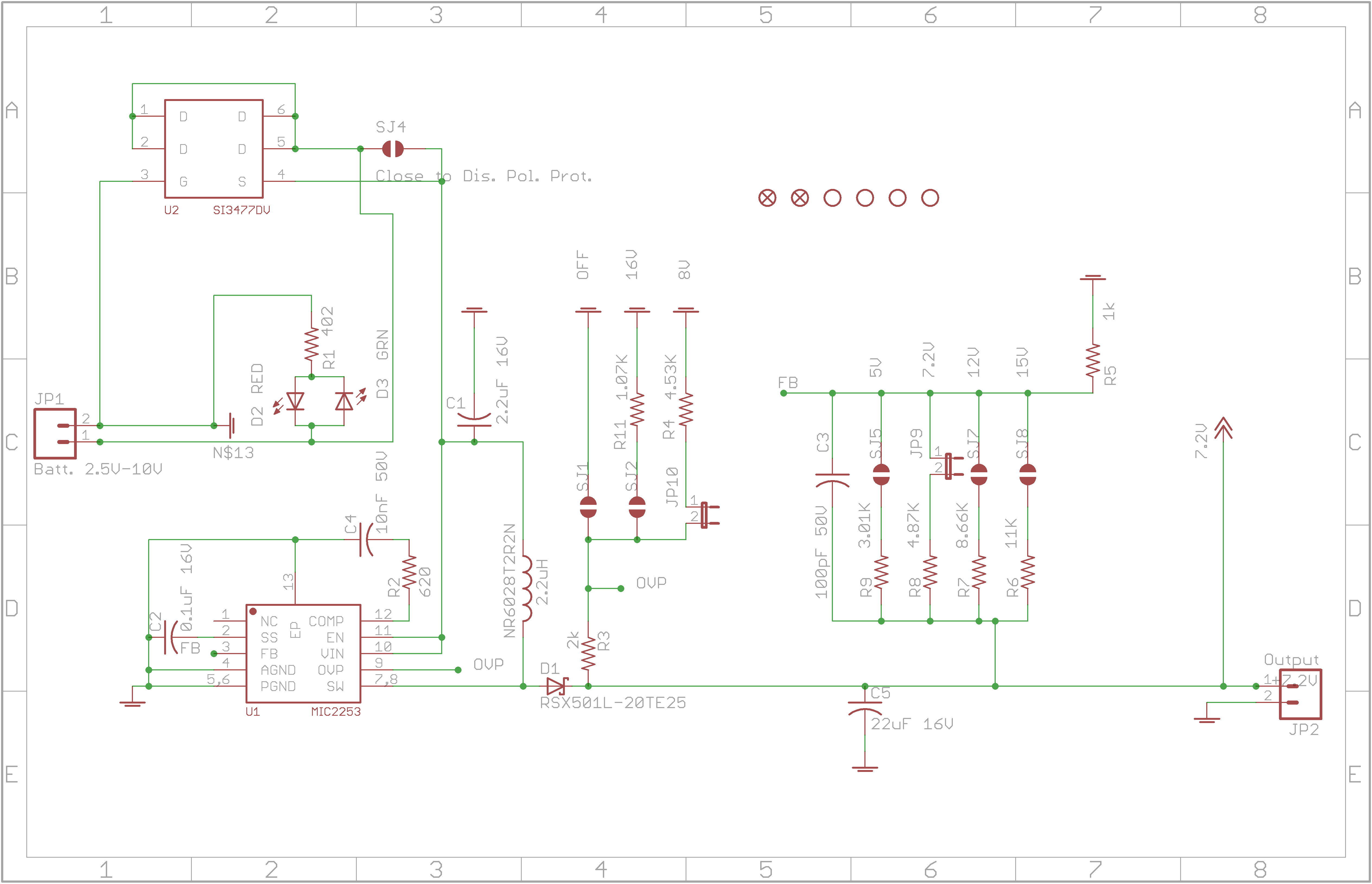
The circuit allows for various combinations of input voltages (Vin) and output voltages (Vout). The current case under debugging involves Vin=3.6V and Vout=7.2V, with a load represented by a 120-ohm resistor. The calculated duty cycle is D=0.5, indicating 50%,...
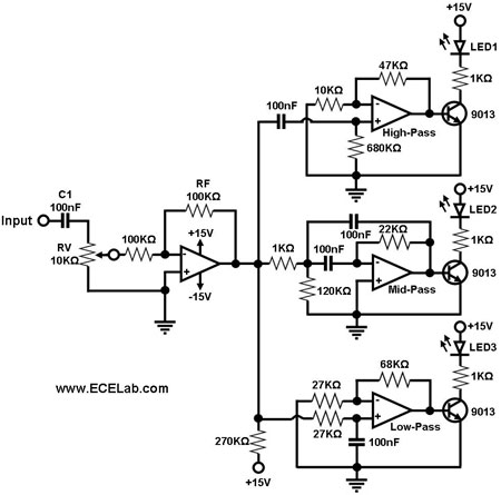
The simple circuit for converting an audio signal. The circuit basically consists of a buffer/amplifier stage and three filter circuits. The audio signal conversion circuit is designed to process audio signals efficiently while maintaining signal integrity. The circuit architecture includes...
The circuit presented on this page attempts to be an interface to convert pulses such as provided by a Basic Stamp or R/C receiver to a dual PWM (Pulse Width Modulation) signal required by an H-bridge. The simplest circuit...
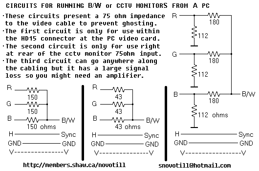
Often you can get away with running a monochrome monitor on GREEN, but this looks real crappy when viewing color images. These simple resistor networks allow you to display R+G+B on a B/W or CCTV monitor without ghosting. Be...