
Mosfet Amplifier OTL 100W by K1058J162

The described circuit employs a 220µF capacitor in conjunction with two diodes to create a controlled power-on sequence for audio amplification systems. The primary function of the capacitor is to store energy, which allows for a gradual increase in voltage across the output when the circuit is powered on. This gradual ramp-up helps to prevent sudden surges of current that can lead to unwanted thumping sounds through the connected speakers, particularly during the initial charging phase of the output capacitor.
The inclusion of diodes serves to direct the current flow in a manner that further smooths the power-on characteristics. By allowing the capacitor to charge through the diodes, the circuit can mitigate any abrupt changes in voltage that may occur when the system is first activated. This is particularly important in high-fidelity audio applications, where even minor disturbances can be audible and negatively impact the listening experience.
In scenarios involving bi-amping or tri-amping setups, where multiple amplifiers are used to drive different frequency ranges, the role of this circuit becomes even more critical. Active crossover filters are often employed in such systems to divide the audio signal into separate frequency bands, directing them to the appropriate drivers. Without the gradual power-on feature, low-frequency signals could inadvertently reach high-frequency drivers, potentially causing damage or distortion.
In summary, the circuit's design, featuring a 220µF capacitor and dual diodes, is a thoughtful approach to enhancing audio quality by ensuring a smooth power-on experience, particularly in sensitive or complex audio systems. This consideration is essential for maintaining the integrity of sound reproduction and preventing any undesirable artifacts during operation.This includes a 220uF capacitor and two diodes to slow down the switch-on to reduce the output thump as the output capacitor charges through the speaker. This is not essential, depending on speaker sensitivity, with my own speakers there is just an unobtrusive low frequency sound at switch-on.
With other applications such as a bi-amp or tri-amp sy stem with active crossover filters, this addition may become more useful to avoid low frequencies reaching high frequency speaker drivers. It may also have some point if a high sensitivity speaker is used, so it makes sense to include it in this low noise version.
Disclaimer All files are found using legitimate search engine techniques. This site does not and will not condone hacking into sites to create the links it list. We will and do assume that all links found on the search engines we use are obtained in a legal manner and the webmasters are aware of the links listed on the search engines. If you find a URL that belongs to you, and you did not realize that it was "open to the public", please use the report button to notify the blogmaster of your request to remove it or it will remove within 24 hours.
This is not an invitation for webblog haters to spam with requests to remove content they feel that is objectionable and or unacceptable. Proof of URL ownership is required. NOTICE: This Blog Has Already Been Reviewed And Accepted By Blogger. com 🔗 External reference
Related Circuits
Amplifying weak radio signals presents the challenge of also amplifying noise. The ability to receive signals is contingent on the level of background noise, which can include man-made interference or static. In this design, the RF signal first encounters...
The primary component of this circuit is the LM386 amplifier chip. It also incorporates a transistor input to buffer the input signal and provide additional gain for the LM386. This compact unit has proven useful in various scenarios, particularly...
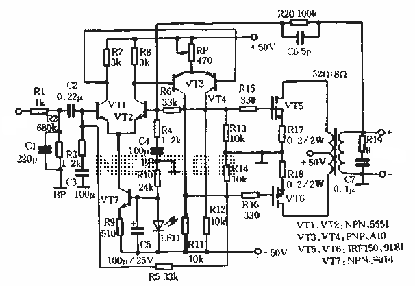
This article describes a transformer-based output FET amplifier, with tonal characteristics similar to those of tube amplifiers. It introduces various effects that are significant for audio enthusiasts. Power amplifier specifications include a rated output power of 50W (with an...
An amplifier circuit utilizing the IC STK4065, which operates solely with this integrated circuit. This series does not have equivalent alternatives in the use of ICs. The power amplifier delivers an output power of 35 Watts, supplied with a...
The aim of this design was to reproduce a Combo amplifier of the type very common in the sixties and the seventies of the past century. It is well suited as a guitar amplifier but it will do a...
This low-cost project enables audio reproduction from a television without disturbing others. It eliminates the need for wired connections between the TV and loudspeakers. Instead, it utilizes invisible infrared light to transmit audio signals from the TV to the...