
Voltage Doubler Circuit with 555
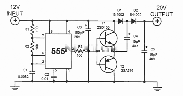
The DC voltage doubler circuit typically employs a configuration using diodes and capacitors. The basic operation involves two stages of rectification and filtering to achieve the desired voltage increase.
In the first stage, an AC input voltage is applied to a capacitor, which charges to the peak voltage of the AC signal. Diodes are used to direct the current flow, ensuring that the capacitor only charges during the positive half-cycle of the AC input.
During the negative half-cycle, the charged capacitor discharges through a second diode into the output load, effectively doubling the voltage across the load. The use of two capacitors in this configuration allows for the accumulation of charge, further enhancing the output voltage.
The output voltage can be calculated based on the input voltage and the characteristics of the diodes and capacitors used in the circuit. It is crucial to select components that can handle the expected voltage and current levels to ensure reliable operation.
This type of circuit is commonly used in applications such as battery-powered devices, where maximizing voltage from a limited power supply is essential. It is also utilized in signal processing and communication systems where specific voltage levels are required for proper functionality.
Overall, the DC voltage doubler circuit is a practical solution for obtaining higher voltage levels from a lower voltage source, making it an important component in various electronic designs.This dc voltage doubler circuit produces a voltage that is twice its voltage supply. This is useful when a higher voltage level is needed out of a single lower voltage power supply. Since the current consumption levels are low in such cases.. 🔗 External reference
Related Circuits
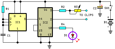
The current generated flows through clips placed on the earlobes. The output current is adjustable from 80 to 600 microamperes, following the recent launch in Europe. The described device utilizes a current generation mechanism that delivers a controlled microcurrent through...
Power an RS232-TTL converter circuit using the serial port to eliminate the need for an external power supply. It has been noted that the DTR, RTS, and TD pins can facilitate this. Since the TD pin is already utilized...
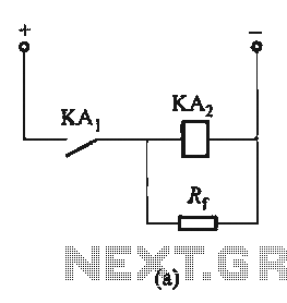
The circuit depicted in Figure 6-24 includes a relay coil with both ends connected in parallel to either a resistor Rf or an auxiliary diode VD. This configuration is equivalent to providing power after a short circuit, which increases...
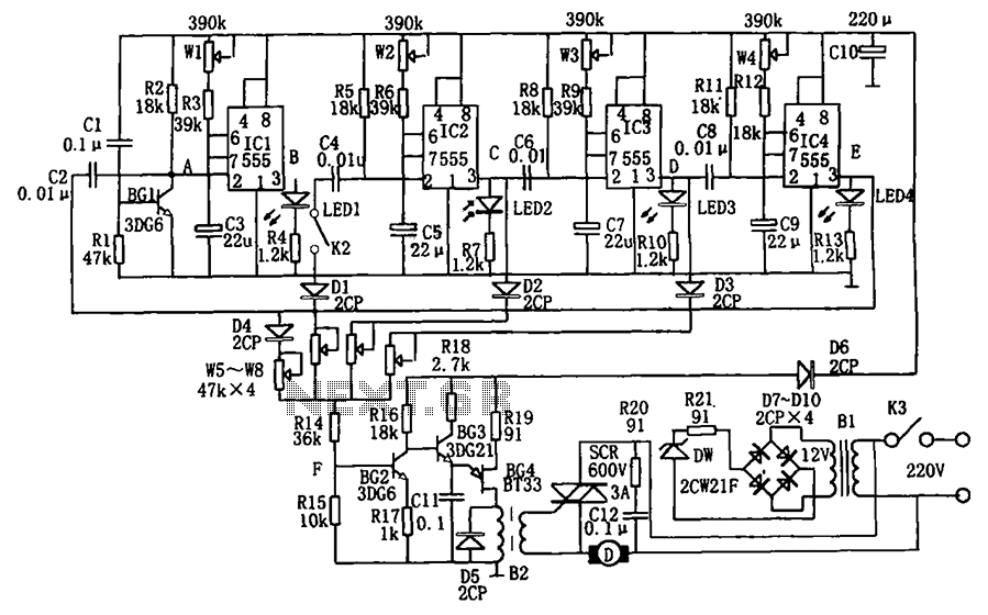
The circuit depicted in the figure is a wind speed programmable circuit. It includes a step-down rectifier circuit, a multi-stage cycle timing circuit, a phase shift control circuit, and a thyristor control circuit. The buck rectifier provides a DC...
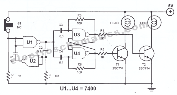
The principle utilized in this electronic head or tail circuit is straightforward: a multivibrator controls a flip-flop. The multivibrator oscillates as long as the button S1 is pressed, while the flip-flop toggles on and off at a frequency of...
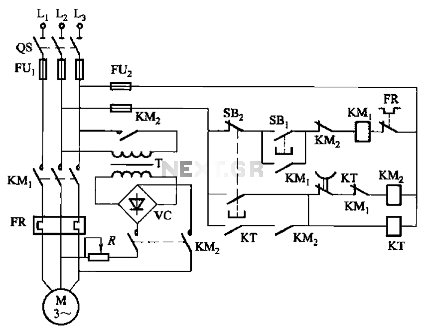
The circuit depicted in Figure 3-135 employs a time relay (KT) to determine the braking time. The circuit utilizes a time relay, which is a crucial component for controlling the duration of the braking process. The time relay KT is...
Warning: include(partials/cookie-banner.php): Failed to open stream: Permission denied in /var/www/html/nextgr/view-circuit.php on line 713
Warning: include(): Failed opening 'partials/cookie-banner.php' for inclusion (include_path='.:/usr/share/php') in /var/www/html/nextgr/view-circuit.php on line 713