
voltage conversion circuit composed of NJM4558
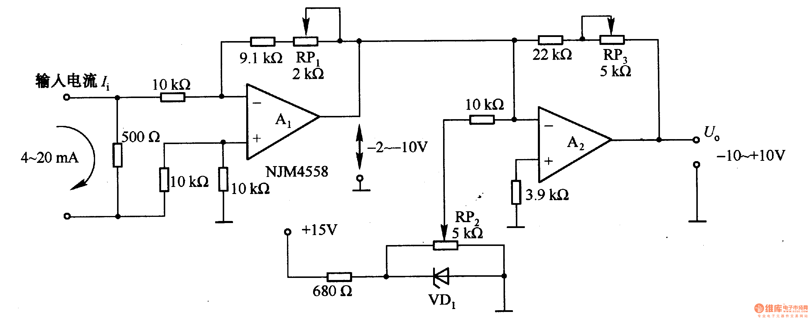
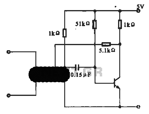
The voltage/current conversion circuit depicted in Figure 1-42 (a) employs a precision operational amplifier (op-amp) configured in a non-inverting mode to achieve the desired conversion characteristics. The input voltage, varying from 0 to 10V, is fed into the non-inverting terminal of the op-amp. The circuit incorporates a feedback resistor network, including RP2, which is crucial for calibrating the output current. When RP2 is adjusted to set the input voltage to 0V, the op-amp output drives the current through a transducer or load, resulting in a maximum output current of 20mA. Conversely, when the input voltage reaches its maximum of 10V, the output current is reduced to 4mA, demonstrating the linear relationship between input voltage and output current over the specified range.
In Figure 1-42 (b), the current/voltage conversion circuit is designed to convert the 4-20mA current signal into a corresponding output voltage that spans from -10V to +10V. This circuit typically utilizes a differential amplifier configuration, allowing it to accurately process the current input. The output voltage is achieved through a combination of resistors that set the gain and offset of the amplifier. The resistor adjustments, including those of RP, enable fine-tuning of the output voltage, ensuring that the conversion is linear and adheres to the desired output range. This type of conversion is essential in industrial applications where current loops are standard for transmitting sensor data, and converting these signals into voltage levels is necessary for further processing or display.
Overall, both circuits exemplify critical techniques in signal conversion and conditioning, facilitating interoperability between different electronic systems and enhancing measurement accuracy in various applications.Figure 1-42 (a) is a voltage / current conversion circuit, and it can convert 0-lOV input voltage into 4-2OmA output current. Adjusting RP2 could make Ui = 0, I. = 2OmA; adjusting RP2 could make Ui = lOV, I. = 4mA. Figure 1-42 (b) is the current / voltage conversion circuit, which will convert the 4-2OmA current into -10 to + lOV output voltage.
Adjusting RP.. 🔗 External reference
Related Circuits
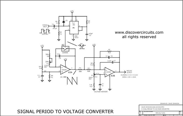
This circuit is designed to convert a square wave input signal into a voltage output. The voltage produced is proportional to the time interval between the edges (period) of the signal, rather than its frequency. The operational range of...
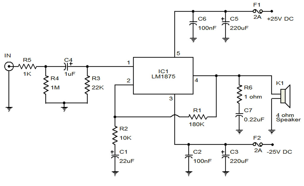
The circuit illustrates a 20-Watt audio amplifier diagram based on the LM1875 integrated circuit (IC). It is designed for use in automotive applications and provides an output power of 20 Watts. The 20-Watt audio amplifier circuit utilizing the LM1875 IC...
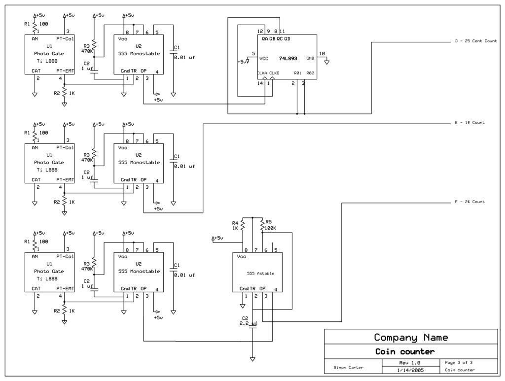
The next counter section operates similarly but is designed to count four quarters, single $1 coins (loonies), and single $2 coins (toonies). The circuit for the toonies is configured. The circuit for the counter section includes a digital counting mechanism...
This circuit illustrates an oscillator that is controlled by an optocoupler, utilizing photoelectric coupling to drive a transistor. The oscillator circuit described operates by employing an optocoupler to provide electrical isolation between its input and output stages while allowing control...
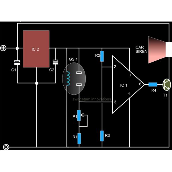
A straightforward smoke detector circuit has been presented through a schematic diagram, which can be easily constructed and installed in an area for essential detection purposes. The circuit utilizes the versatile FIGARO TGS 813 gas sensor as the primary...
This simple flashing light circuit operates at 6 volts and 0.5A, exhibiting low current consumption when the light bulb is turned off. The frequency of the flashing is predetermined. The circuit consists of a power supply, typically a battery or...