
Voltage InverterII
The described circuit utilizes a charge pump configuration to generate dual output voltages from a single input voltage source. This is particularly advantageous in applications where space and cost are critical, such as in portable devices powered by batteries.
The circuit typically consists of a few key components: capacitors, diodes, and an integrated circuit (IC) designed for voltage inversion. The input voltage is connected to the IC, which alternates the charge and discharge cycles, allowing the circuit to generate both positive and negative voltages. The output capacitors smooth the resultant voltage, ensuring a stable and usable power supply.
For an input voltage range of 5V to 20V, the output voltage can be adjusted by selecting appropriate capacitor values and the specific IC used. Commonly, the output will be set to ±2.5V for lower input voltages and can reach up to ±10V for higher input voltages. This flexibility makes the circuit suitable for a variety of applications, including operational amplifiers, analog signal processing, and other electronic components that require dual polarity power supplies.
The design should also consider the load current requirements, as the performance of the charge pump can vary based on the load connected to the output. It is essential to ensure that the selected components can handle the expected current without significant voltage drop or overheating. Additionally, filtering capacitors may be included at the output to further stabilize the voltage and reduce noise, enhancing the overall performance of the circuit.
In conclusion, this dual voltage generation circuit is a practical solution for powering devices that require both positive and negative voltages from a single supply, offering simplicity, cost-effectiveness, and versatility in design.This simple and inexpensive circuit can produce a dual (positive and negative) voltage from a single supply input. It is therefore extremely useful for powering opamp and other circuits that require a dual voltage from a single battery.
The circuit will operate at an input voltage from around 5V to 20V and produce a output from +-2.5V to +-10V. 🔗 External reference
Related Circuits
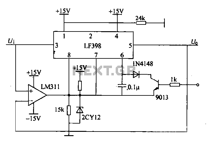
The peak voltage sample and hold circuit is illustrated in Figure 12-50. This circuit comprises the LF398 sample and hold chip and the LM311 voltage comparator. The LF398 is responsible for outputting and inputting voltages. The LM311 compares the...
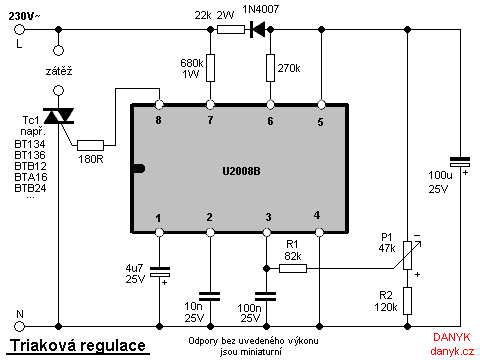
Triac regulation is designed to control the power of mains appliances. It can adjust the brightness of incandescent light bulbs, halogen lamps, dimmable energy savers, heaters, and other thermal devices, as well as regulate motors. The power can be...
This circuit is a dual voltage regulated power supply, +12, -12, 0 volt. It uses the 7812 and 7912 regulators. You need a 18VCT, 1A transformer at input. More: Caution: Input / Ground are reversed between the 7812 and...
This circuit regulates a DC power output and has a wide range of applications. It can be utilized to control the speed of a motor, a pump, a toy train, or the brightness of an LED or lamp. Essentially,...
There are two regulator circuits that utilize the L200 integrated circuit from SGS-Thomson to regulate voltage and current. In circuit Fig. 1, the output voltage can be adjusted using the variable resistor RV1. In Fig. 2, both output voltage...
The 5 volt regulated power supply for TTL and 74LS series integrated circuits has to be very precise and tolerant of voltage transients. These ICs are easily damaged by short voltage spikes. A fuse will blow when its current...