
Voltage Level Indicators for battery Using LM324
The circuit operates by leveraging the LM324 operational amplifier, which is configured in a comparator mode. The reference voltage is set using a voltage divider network that establishes a threshold for the battery voltage. The output from the LM324 is connected to the base of the C9013 transistors, which are configured in a common-emitter arrangement. This configuration allows the transistors to act as switches that control the current flowing through the LEDs.
The four LEDs are strategically positioned to provide a clear indication of the battery voltage status. The green LEDs correspond to higher voltage levels, indicating that the battery is in good condition. As the voltage drops, the operational amplifier's output changes state, causing the transistors to turn off the green LEDs while turning on the red LED when the voltage falls below the specified thresholds.
The circuit is designed to be simple yet effective, providing a visual representation of battery health. It is suitable for various applications where monitoring battery voltage is essential, such as in battery-powered devices and solar power systems. The use of the LM324 IC ensures low power consumption, making this circuit efficient for continuous operation. Proper heat dissipation should be considered for the transistors to ensure reliable performance over time.This circuit is a circuit diagram of an indicator to show battery voltage 12 volts. Working principle of this circuit is the battery voltage compared with the reference voltage. By using the LM324 IC, which is a type LM324 Low Power Quad Operational Amplifier, so that the circuit this time is to use a single IC chip. The output of OP-amp, then con nect with the C9013 transistors, these transistors act as switches to turn on and turn off the LED. Voltage level indicated by four lights led. For ease of reading led arranged in a vertical array. Selected the top three headed green LED while the lower was the most selected red color. If the battery voltage continues to decline (because of usage), then-Led Led will die in sequence from top to bottom. Until the battery when the voltage is below 11. 83 volts then the red led light only means that the battery charges. Red LED will die if the program continues until the voltage falls below 11. 5 volts. The following is a schematic drawing: 🔗 External reference
Related Circuits
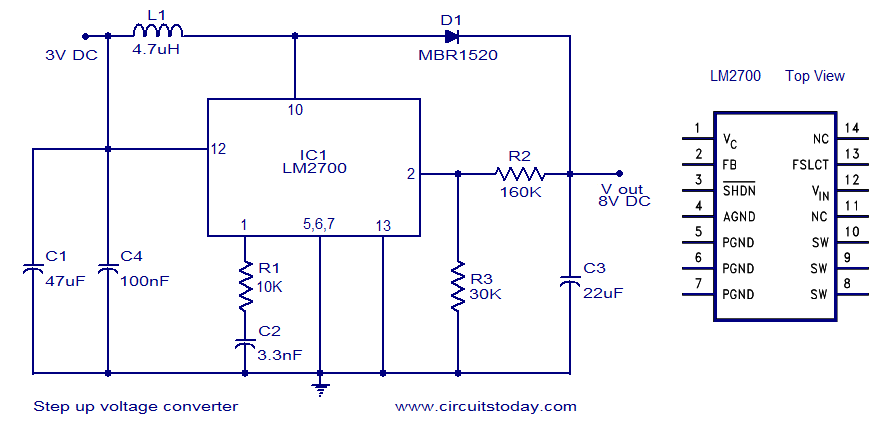
A simple DC to DC step-up voltage converter circuit schematic using the LM2700, which is a step-up switching converter. The LM2700 is a versatile step-up switching converter designed to efficiently convert a lower input voltage to a higher output voltage....
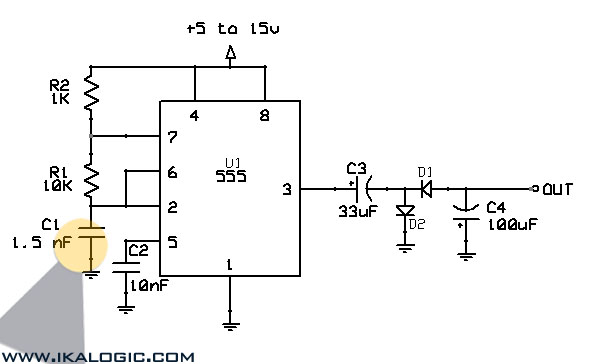
This voltage-to-frequency converter circuit features a voltage-controlled oscillator with a deviation of 0.5%. The integrated circuit IC1 functions as a multivibrator, generating rectangular impulses of equal width. The output frequency is adjustable via the U1 voltage. The D3 diode...
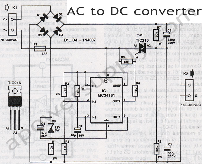
Leaving aside the complex chargers, "stuffed" electronics capacitor charger is one of the best connections. Charging current is limited by the resistor (or other element of the changing excess energy into heat), but the reactance of the capacitor to...
This circuit converts a positive voltage to a negative voltage, resulting in a loss of approximately 1.5 V. For instance, supplying 9 V to the circuit yields an output of -7.5 V. Additionally, this circuit can function as a...
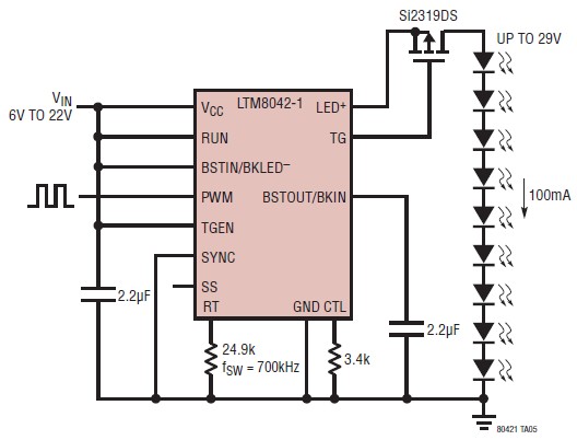
The LTM8042 integrates a boost power topology with a unique current loop to function as a constant-current source. The PWM input allows for LED dimming ratios of up to 3000:1, while analog dimming can be achieved with a single...
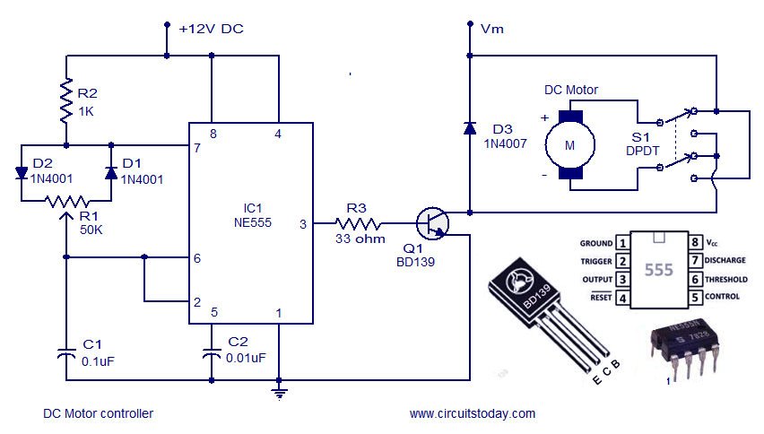
A DC motor controller based on an NE555 timer is presented here. The direction of rotation of the DC motor can also be changed using this DC motor speed control circuit. The described circuit utilizes the NE555 timer IC in...