
Voltage-Programmable Current Source
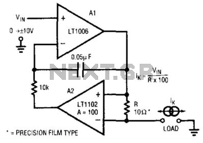
This programmable current source circuit is designed for applications requiring precise current delivery. The LT1102 operational amplifier serves as the main driver, providing the necessary gain and output characteristics to control the current through the load effectively. The inclusion of the LT1006 operational amplifier enhances the circuit's performance by enabling accurate current sensing and feedback control.
A key feature of this circuit is its ability to maintain stable operation across a range of load conditions. The feedback loop created by A2 allows for real-time adjustments to the output current based on the sensed value, ensuring that the output remains consistent despite variations in load resistance.
The choice of a 10-ohm resistor in the feedback path is critical, as it directly influences the output current magnitude. The 0.05 µF capacitor, in combination with the resistor, establishes the frequency response, allowing the circuit to respond effectively to dynamic changes in the load. This configuration is particularly useful in applications such as sensor excitation, LED driving, and precision measurement systems where current stability is paramount.
Overall, the combination of the LT1102 and LT1006 operational amplifiers, along with the carefully selected passive components, results in a robust and versatile programmable current source suitable for various electronic applications. This, circuit is a programmable current source in which op amp LT1102 (Linear Technology Corp.) is used in conjunction with LT1006 op amp. Al, biased by V^, drives current through R (10 ) and the load. A2 senses this current and controls Al. The 10-1 resistor and 0.05-/iF capacitor sets the frequency response of the circuit. 🔗 External reference
Related Circuits
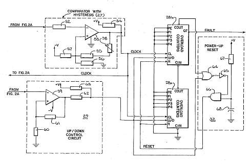
This motor overload circuit allows for short-term overdriving of a system, which is dependent on heat buildup. An overload detection circuit safeguards the motor against currents exceeding the rated current for specific exposure durations. The permissible exposure times are...
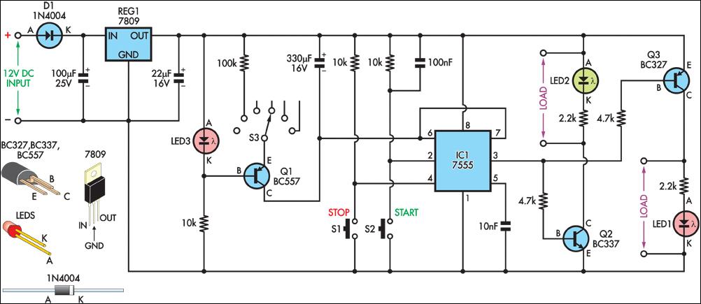
This design will appeal to technicians working with pneumatically operated valves and other devices controlled by a 4-20mA current loop. While 4-20mA signal injectors and calibrators are available, this particular model is cost-effective to construct and user-friendly. Upon initial...
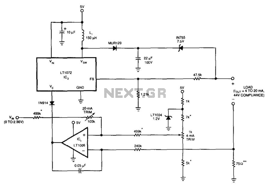
This 5-V circuit employs a servo-controlled DC/DC converter to generate the compliance voltage necessary for current requirements. It is designed to drive 4 to 20 mA into loads as high as 2200 ohms with 44 V of compliance. The...
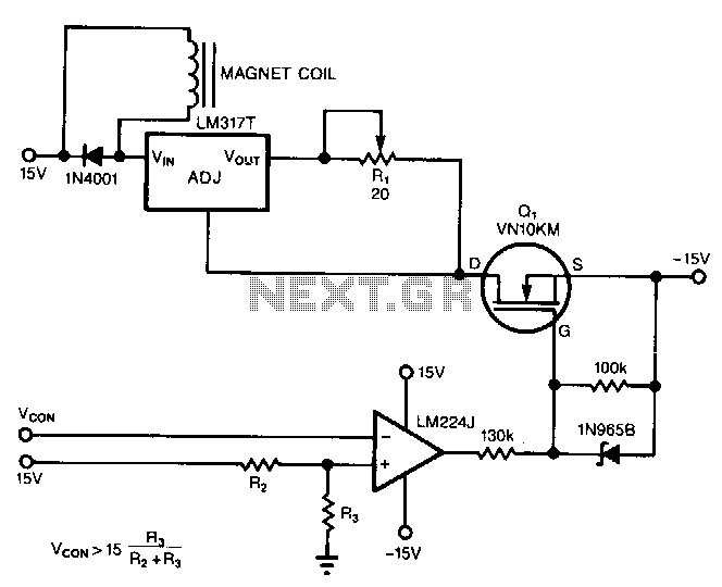
The circuit powers the load through the input of the regulator rather than its output. Due to the presence of a constant dummy load (R1) at the regulator's output, it attempts to draw a constant amount of current, regardless...
An output of 4 mA to 20 mA that is linearly proportional to the input voltage is provided by the current transmitter. Line rejection is included. The current transmitter operates within a specified range, providing an output current that is...
A high voltage power supply is a valuable source that can be effectively used in various applications, such as biasing gas-discharge tubes and radiation detectors. This type of power supply can also serve as a protective measure, such as...