
Voltage regulator for projection lamp
This circuit design is focused on maintaining a stable output voltage for a projection lamp, ensuring optimal performance across a range of input voltages. The use of TRIAC Q3 allows for effective control of the lamp voltage by adjusting its conduction angle, which is crucial for achieving the desired output voltage. The feedback mechanism, which relies on sensing the light output of the lamp, ensures that any variations in the lamp's brightness are compensated for by adjusting the firing of the TRIAC.
The full-wave bridge rectifier plays a vital role in synchronizing the circuit with the AC line, converting the incoming AC voltage into a usable DC voltage for the control circuitry. Zener diode D5 is strategically placed to protect the firing circuit from voltage spikes, ensuring reliable operation. The charging rate of capacitor C1 is critical in determining how quickly the circuit can respond to changes in the input voltage, influencing the timing of the TRIAC's firing.
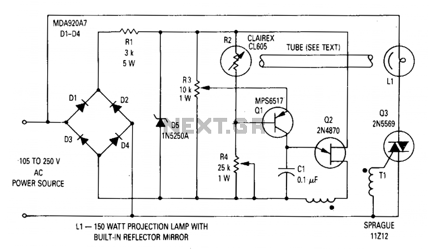
Photocell R2 serves as a variable resistor that adjusts based on the ambient light conditions, allowing for dynamic control of the lamp's brightness. The inclusion of potentiometers R3 and R4 provides a means to fine-tune the output voltage to the desired level, accommodating variations in the line voltage. This flexibility is essential for applications where consistent lighting is required, such as in projection systems. Overall, this circuit exemplifies a well-engineered solution for voltage regulation in lighting applications, combining feedback control, phase control, and protective measures to ensure optimal performance.The circuit will regulate the rms output voltage across the load (a projection lamp) to 100 volts ±2% for an input voltage between 105 and 250 volts ac. This is accomplished by indirectly sensing the light output of lamp LI and applying this feedback signal to the firing circuit (Ql and Q2) which controls the conduction angle of TRIAC Q3.
The lamp voltage is provided by TRIAC Q3, whose conduction angle is set by the firing circuit for unijunction transistor Q2. The circuit is synchronized with the line through the full-wave bridge rectifier. The voltage to the firing circuit is limited by zener diode D5. Phase control of the supply voltage is set by the charging rate of capacitor Cl. Q2 will fire when the voltage on Cl reaches approximately 0.65 times the zener voltage. The charging rate of Cl is set by the conduction of Ql, which is controlled by the resistance of photocell R2. Potentiometers R3 and R4 are used to set the lamp voltage to 100 volts when the line voltage is 105 volts and 250 volts, respectively.
🔗 External reference
Related Circuits
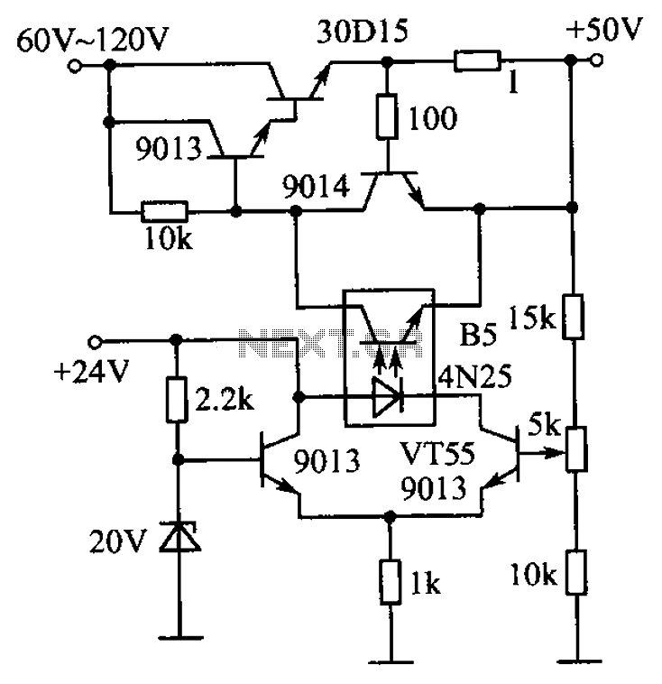
The circuit is illustrated. A standard driving transistor requires a higher breakdown voltage transistor (such as the FIG driving tube 9013). As the output voltage rises, the bias on VT55 increases, leading to an increase in the forward current...
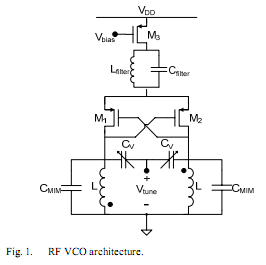
The oscillator is designed to tune from 1.8 GHz to 2 GHz for typical cellular telephony applications. An extended tuning range can be obtained by adjusting the ratio between the varactor capacitance and fixed capacitance in the tank. PMOSFETs...
There is no PCB since there are no components to mount on one. The object was to create a source of ultraviolet light as fast as possible. The UV tubes I bought from a lighting shop for use with...
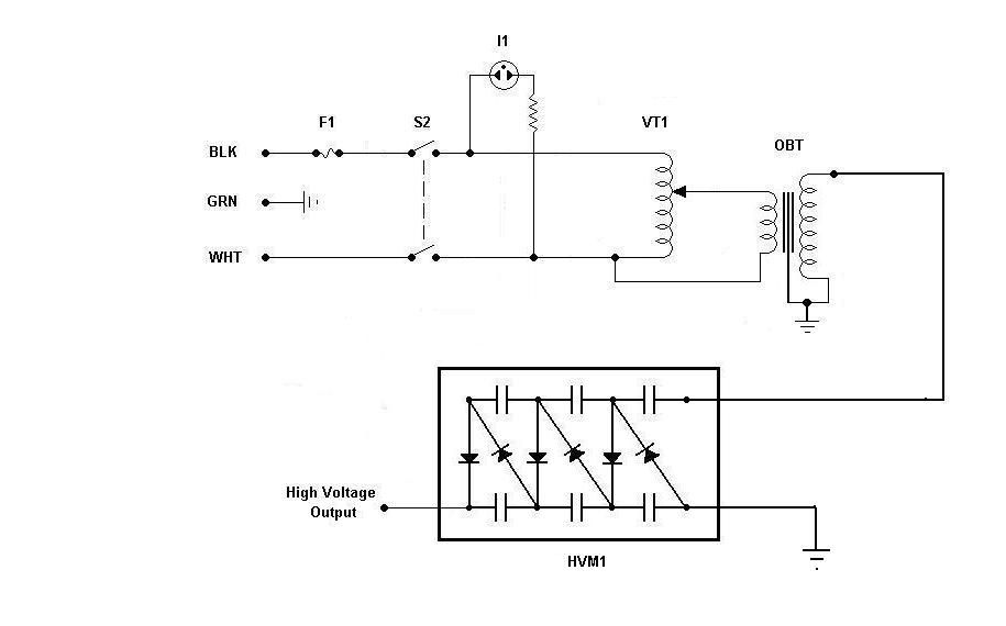
Using components from old microwave ovens, TV sets, and oil burners, it is possible to construct an economical instrument capable of producing high voltage outputs. The primary element in this setup is a voltage multiplier, which should be assembled...
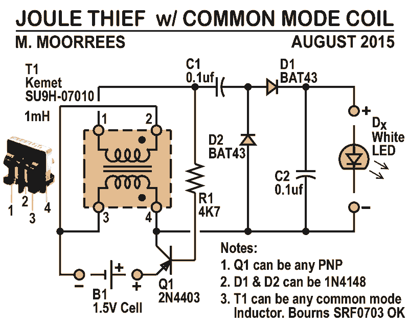
Like all joule thieves, this circuit boosts the voltage from a single 1.5V dry cell battery high enough to illuminate ultrabright GaN blue, green, or white LEDs. Instead of requiring a custom coil, it utilizes an off-the-shelf standard Kemet...
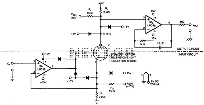
This amplifier can transfer DC to 5 MHz signals across a potential difference of 25,000 V. It can be utilized in CRT displays and high-voltage applications. It is important to note that the tube must be shielded due to...