
Vox AC 50/4 Amplifier
The circuit in question represents a basic Vox AC amplifier. The primary function of this circuit is to amplify the input audio signals, specifically alternating current (AC) signals, and output them to a speaker or other audio output device.
Despite the lack of clarity in the circuit diagram, it can be inferred that the amplifier follows the standard structure of an AC amplifier, which typically consists of three stages: the preamplifier stage, the driver stage, and the power amplifier stage.
The preamplifier stage is responsible for the initial amplification of the input signal. This stage often includes a voltage amplifier to increase the signal's amplitude. The driver stage serves as an intermediary between the preamplifier and power amplifier, providing the necessary current gain to drive the power amplifier. Finally, the power amplifier stage provides the final boost in signal strength before it is outputted to the speaker.
The Vox AC amplifier is popular among musicians for its warm tone and rich harmonics, which are achieved through the use of vacuum tubes in the amplification stages. The circuit likely includes these vacuum tubes, along with other essential components such as resistors, capacitors, and transformers.
Without a clearer circuit diagram, it is difficult to provide a more detailed description of the specific components and their arrangement within the circuit. However, this general description should provide a basic understanding of the Vox AC amplifier's function and structure.This is an simple Vox AC amplifier. The circuit is not very clear but is readable. 🔗 External reference
Related Circuits
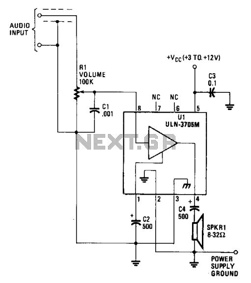
The amplifier functions with supply voltages up to 12 volts and can operate at lower voltages as low as 1.8 volts while maintaining acceptable distortion levels, albeit with reduced volume. Its power requirements make it suitable for applications powered...
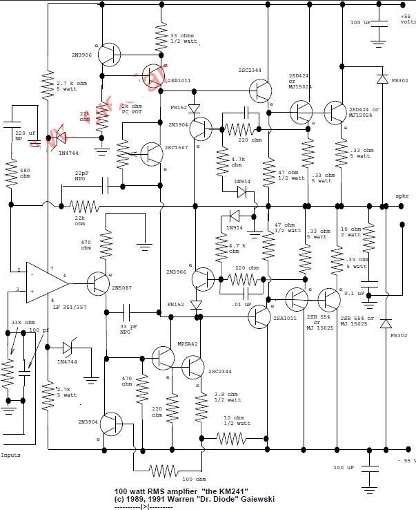
This is a 100-watt basic power amplifier designed to be relatively easy to build at a reasonable cost. It offers better performance, or musical quality, than the standard STK module amplifiers commonly found in mass-market stereo receivers. The design...
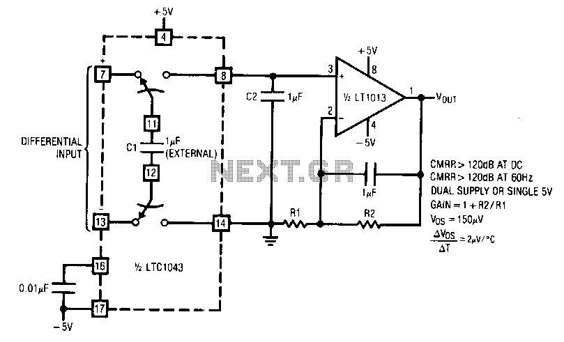
LTC1043 and LT1013 dual operational amplifiers are utilized to construct a dual instrumentation amplifier with only two packages. A single double-pole double-throw (DPDT) switch converts the differential input into a ground-referenced single-ended signal at the input of the LT1013....
Circuit stereo TDA2822 audio power amplifier circuit schematics. In this series, the TDA2822M IC is utilized as the primary amplifier. Additionally, alternatives such as KA2209 and NJM2073 can also be employed. The TDA2822 audio power amplifier circuit is designed to...
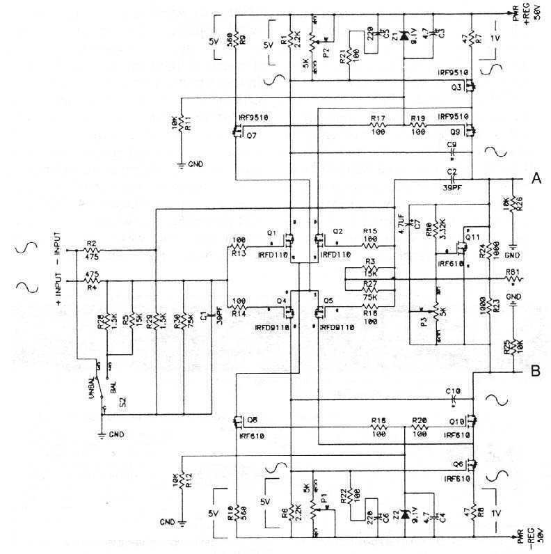
The MOSFETS we are dealing with are three terminal devices which are used to control electron flow in a circuit. Two of the pins (the source and drain) pass the current, and the third pin (the gate) is used...
The following circuit illustrates an audio amplifier circuit diagram with a power output of 25 watts. Features include its widespread use in nearly all mass-market stereo receivers produced, providing enhanced sound quality. This audio amplifier circuit is designed to deliver...