
Sound-Activated Lamp (Relay Switch)

The circuit utilizes a sound sensor, which is typically a microphone or a piezoelectric sensor, to detect sound waves. Upon detecting a sound above a predetermined threshold, the sensor generates an output signal. This output signal is then used to trigger a transistor or a relay, which serves as the switch in the circuit.
In detail, the sound sensor is connected to an amplifier circuit to ensure that even low-level sounds can be detected. The amplified signal is then fed into a comparator circuit that compares the sensor output with a reference voltage. When the sound level exceeds the reference, the comparator output goes high, activating the transistor or relay.
The transistor acts as a low-side switch, controlling the power to a load, which could be a light, motor, or any other electronic device. If a relay is used, the sound detection can control larger loads that require higher voltage or current than the transistor can handle.
Power supply considerations are also essential; typically, a battery or a regulated power supply is used to ensure consistent operation. Additionally, capacitors may be included in the circuit to filter noise and stabilize the voltage levels.
This sound-activated switch circuit is versatile and can be adapted for various applications, including automatic light control, sound-activated alarms, or even as a trigger for more complex systems in robotics or home automation.This simple circuit shown int the schematic diagram actives the switch using sound. We can use this circuit for various applications, such as automatic (s.. 🔗 External reference
Related Circuits
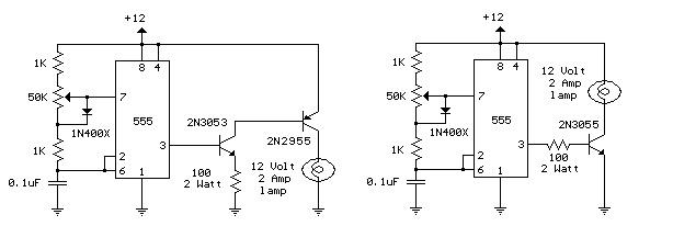
Here is a 12 volt / 2 amp lamp dimmer that can be used to dim a standard 25 watt automobile brake or backup bulb by controlling the duty cycle of an astable 555 timer oscillator. When the wiper...
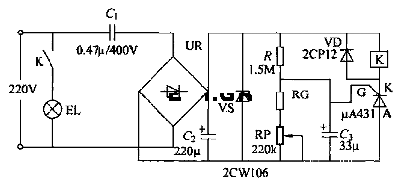
The circuit utilizes a 220V AC voltage input that is processed through a capacitor (C1) for bucking, followed by a rectifier bridge (UR) which acts as a barrier-wave rectifier. A filter capacitor (C2) is used to smooth the output...

Ideal for operating 3 to 24V DC existing on-circuit lamps. This circuit was designed to provide continuous light for lamps already wired into a circuit. The circuit is intended to facilitate the operation of existing DC lamps that are integrated...
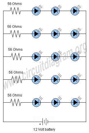
This project involves a 12V LED lamp circuit that is notably simple. The circuit comprises five resistors and fifteen super bright white 5mm LEDs, which are readily available at low prices. It is compatible with any type of 12-volt...
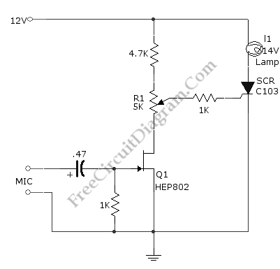
This simple circuit, as shown in the schematic diagram, activates a switch using sound. It can be utilized for various applications, such as automatic sound-controlled disco lights or a car's LED light show. The transistor Q1 amplifies the audio...
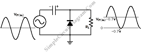
A diode and capacitor can be utilized to clamp an AC signal, shifting the level into the positive region for all cycles. This condition is sometimes necessary to ensure a positive output. In an electronic circuit, clamping is a technique...
Warning: include(partials/cookie-banner.php): Failed to open stream: Permission denied in /var/www/html/nextgr/view-circuit.php on line 713
Warning: include(): Failed opening 'partials/cookie-banner.php' for inclusion (include_path='.:/usr/share/php') in /var/www/html/nextgr/view-circuit.php on line 713