
VSWR METER
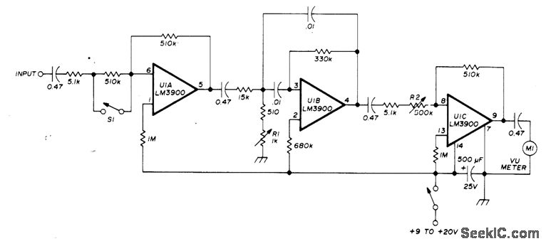
The VSWR meter is designed to provide accurate measurements of voltage standing wave ratio (VSWR) in radio frequency applications. The high-gain amplifier enhances the input signal, allowing for better resolution of low-level signals that are typically encountered in VSWR measurements. The selective amplifier, with its narrow bandwidth of 100 Hz, ensures that only the desired signal frequency of 1000 Hz is processed, effectively filtering out unwanted noise and interference.
The variable-gain output amplifier allows the user to adjust the output signal to suit the sensitivity of the connected VU meter. This flexibility is crucial for adapting to different measurement environments and signal strengths. The low-cost VU meter serves as a visual indicator of the VSWR, providing an easy-to-read output for users.
The current draw of approximately 6 mA from a 9 V battery makes this design energy-efficient, allowing for prolonged use in field applications without frequent battery changes. The inclusion of switch S1 to increase the gain is particularly useful for low-level signals, enhancing the meter's capability to detect and display small variations in VSWR.
Resistor R1 plays a critical role in setting the frequency of the selective amplifier, ensuring that it is accurately tuned to the desired frequency of 1000 Hz. Meanwhile, resistor R2 is essential for calibrating the VU meter, allowing for precise readings that are essential for effective antenna matching and system optimization.
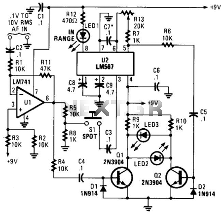
Overall, this VSWR meter design is a practical tool for radio amateurs and professionals alike, facilitating the analysis and tuning of VHF/UHF antennas with ease. Its compact size, low power consumption, and user-friendly features make it an invaluable asset in the field of radio frequency engineering.Simple, easily transported VSWR meter consists of high-gain amplifier, narrow-bandwidth (100-Hz) selective amplifier tuned to 1000 Hz, and variable-gain output amplifier driving low-cost VU meter. Ideal for nulling type VSWR measurements. Draws only about 6mA from 9. V transistor battery. Closing S1 increases gain about 100 times for Iow. Ievel read ings. R1 sets U1B to 1000 Hz, while R2 sets reference on VU meter. -J. Reisert Matching Techniques for VHF/UHF Antennas, Ham Fladio, July 1976, p50-56. 🔗 External reference
Related Circuits
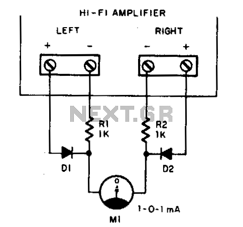
Play any stereo disc or tape and then set the amplifier to mono. Adjust the left and right channel balance until meter Ml indicates zero; then the left and right output levels are identical. To implement a system that allows...
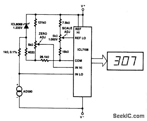
This circuit allows for zero adjustment as well as slope adjustment. The ICL8069 brings the input within the common-mode range, while the 5 K pots trim any offset at 218 °K (-55 °F) and set the scale factor. The...
This tester is designed to locate stray electromagnetic (EM) fields. It can easily detect both audio and RF signals up to frequencies of around 100 kHz. However, this circuit is not a metal detector, but it can detect metal...
A circuit for measuring levels based on a typical application of National. A measurement circuit designed for level detection typically employs a combination of sensors and signal processing components to provide accurate readings. In this context, the circuit can utilize...
This is an easy-to-build yet highly accurate digital voltmeter designed as a panel meter. It can be utilized in DC power supplies or any application requiring precise voltage readings. The circuit uses the CL7107 Analog to Digital Converter (ADC)...
This meter is unique as it does not utilize a D'Arsonval movement or digital display for frequency readings. Instead, the measured frequency is indicated on a hand-calibrated dial. Any audio signal applied to the circuit is amplified by U1,...
Warning: include(partials/cookie-banner.php): Failed to open stream: Permission denied in /var/www/html/nextgr/view-circuit.php on line 713
Warning: include(): Failed opening 'partials/cookie-banner.php' for inclusion (include_path='.:/usr/share/php') in /var/www/html/nextgr/view-circuit.php on line 713