
VU LED Indicator Schematic
The VU LED indicator circuit is designed to provide a visual representation of audio signal levels, enabling users to monitor the output levels effectively. The circuit employs a logarithmic scale to ensure that the LED responses correspond to human auditory perception, where a logarithmic relationship exists between sound intensity and perceived loudness. The use of a single IC simplifies the design and reduces component count, which is advantageous for both space and cost considerations.
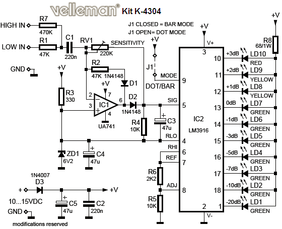
The inclusion of a variable resistor (VR1) allows for fine-tuning of the LED response, ensuring that the visual indicators accurately reflect the audio signal levels being processed. The green LEDs (L1 to L10) are arranged in a sequential manner, with L1 being the lowest level indicator and L10 representing the maximum level. This arrangement provides a clear visual cue to the user regarding the signal strength.
The circuit's ability to operate in either dot or bar mode, selectable via a jumper, enhances its versatility, allowing it to be configured according to user preference or specific application requirements. The design also accommodates variations in input signal levels, particularly when interfacing directly with speaker outputs. The recommended use of a series resistor at the "Aud" input ensures that the circuit remains within operational limits, preventing potential damage to the LEDs or the IC itself.
In summary, this VU LED indicator circuit is an efficient and effective means of monitoring audio signal levels, utilizing a straightforward design that is both compact and cost-effective, making it suitable for various audio equipment applications.VU LED indicator is simpler and smaller than their analog, and very common in audio equipment. This version is based on National Semiconductor IC, and using the logarithmic version. Each LED operates with a 3dB difference from before, and the jumper is provided to allow dot or bar mode. The circuit is completely conventional, and is based on application notes from National Semiconductor. The circuit is shown in the picture below and you can view it with a single IC and some discrete components. DC to the LED is almost filtered - C1 are included to ensure that the IC does not oscillate, and is not a filter cap.
This allows a higher LED current with lower dissipation than is the case if the DC is fully refined, and full smoothing would also require much larger capacitors. This will increase the size and cost of the project - especially important if you want to use in larger quantities that may occur with a mixer or analyzer.
It could not be simpler. At the maximum level that you want to operate the equipment (as shown on the audio millivoltmeter or an oscilloscope with a signal applied), adjust VR1 so that the signal light to all the green LED (L1 is the most sensitive, and L10 showed the maximum level, so L1 to L8 should be lit ). If the input directly from the speaker output, an additional series resistor should be used in terminal "Aud" input to reduce the level.
This can be determined by calculation (I leave it to you) or by experiment. As a guide, for 50W amplifier, an external resistance should be about 47k ohms. If you calibrate the meter for the power amplifier, set the output to a level below clipping. Adjust the level control until the LED turns on. In this way, if (L10) LED bulbs last when you`re listening to music, you`ll know that you are very close to clipping, and volume should be reduced. 🔗 External reference
Related Circuits
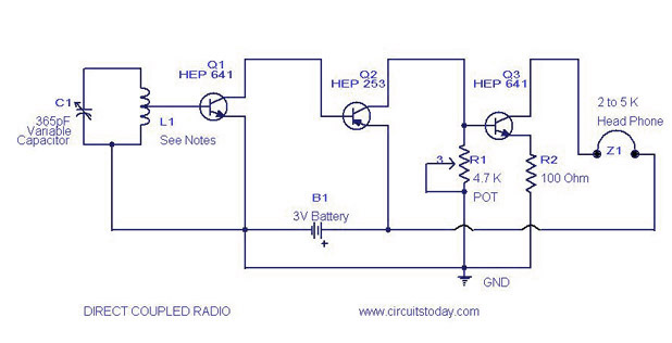
A simple direct-coupled radio circuit diagram and schematic, ideal for adjacent stations. This circuit uses Q1 as an audio amplifier, and the base-emitter capacitance provides radio filtering. The described circuit is a direct-coupled radio receiver designed to effectively operate with...

The Proximity Sensor circuit is illustrated below. Three red boxes indicate the additions to the circuit previously constructed in Part 2: Motor Control. The new components included in the schematic are the GP2Y0A21YK IR Sensor, a headphone speaker, and...
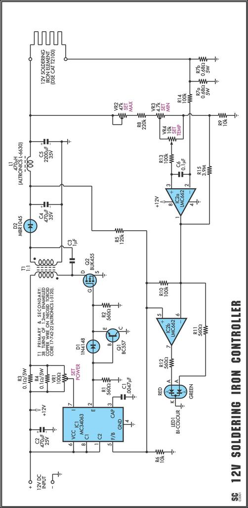
One reason commercial soldering stations are expensive is that they generally require soldering irons with built-in temperature sensors, such as thermocouples. This circuit eliminates the need for a special sensor by sensing the temperature of a soldering iron heating...
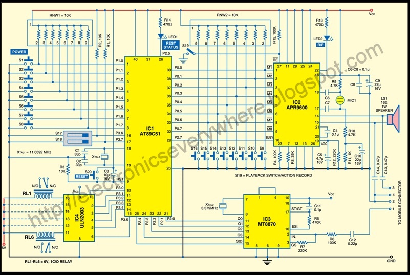
A circuit that allows for the operation of home appliances such as lights and water pumps from a remote location, such as an office. This system enables users to turn off appliances with their cellphones if they forget to...
Below is a comparator circuit that can measure the voltage of a car battery in steps of 1 volt. The voltage indication is achieved through comparison. The comparator circuit designed for measuring the voltage of a car battery utilizes an...
The entire project was developed at the request of a friend. Its purpose is to remotely monitor the water level in a metal tank located in the attic using a simple control unit placed in the kitchen, several floors...
Warning: include(partials/cookie-banner.php): Failed to open stream: Permission denied in /var/www/html/nextgr/view-circuit.php on line 713
Warning: include(): Failed opening 'partials/cookie-banner.php' for inclusion (include_path='.:/usr/share/php') in /var/www/html/nextgr/view-circuit.php on line 713