
SOIL MOISTURE METER
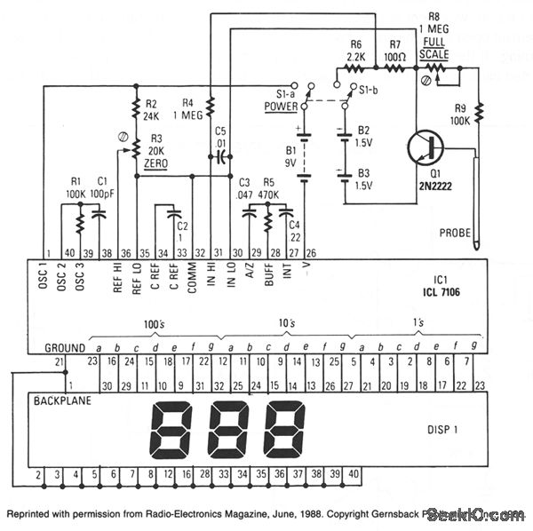
The circuit utilizes the Intersil ICL7106 integrated circuit, which serves as the core component for analog-to-digital conversion and display functionality. The ICL7106 is designed to drive an LCD, providing a clear digital readout of the measurements taken by the probe. The inclusion of a clock and voltage reference within the IC ensures stable operation and accurate conversions.
The probe's design, using lightweight aluminum tubing, enhances portability and ease of use while maintaining structural integrity. The variable resistor sensor is critical for the measurement process, as it directly influences the base current of Q1, a transistor that acts as an amplifier. The collector current of Q1, which is modulated by the sensor's resistance, is then translated into a voltage signal across resistor R7. This voltage is fed into the ICL7106, which converts the analog signal into a digital format for display.
Power consumption is a key consideration in the design, with the LCD operating at a low current draw of around 25 microamperes, and the ICL7106 drawing less than 2 milliamperes. This efficient power management allows the device to be powered by a 9-volt battery or two 1.5-volt AA cells, both of which provide sufficient energy for extended use without frequent battery replacements.
Calibration is a straightforward process, involving the adjustment of potentiometers R3 and R8 to ensure accurate readings. By setting R3 to the center position and immersing the probe in water, the user can calibrate the device to read a standard value of 100. Subsequent adjustments ensure that the device accurately returns to a reading of 000 when removed from the water, confirming the reliability of the sensor and the associated circuitry. This calibration procedure is essential for maintaining measurement accuracy in practical applications.IC1, an Intersil ICL7106, contains an a/d converter, a 3 1/2-digit LCD driver, a clock, a voltage refer-ence, seven segment decoders, and display drivers. A similar part, the ICL7107, can be used to drive seven segment LEDs. The probe body is a five-inch length of light-weight aluminum tubing. The leads from the circuit are connected to the body a nd tip of the probe. The sensor functions as a variable resistor that varies Q1`s base current, hence its collector current. The varying collector current produces a varying voltage across 100 © resistor R7, and that voltage is what IC1 converts for display.
The LCD consumes about 25 A, and IC1 consumes under 2 mA, so the circuit will run for a long time when it is powered by a standard 9-V battery. Current drain of the two 1. 5-V AA cells is also very low: under 300 A. To calibrate, rotate R3 to the center of its range. Then place the end of the probe into a glass of water and adjust R8 for a reading of 100. When you remove the probe from the water, the LCD should indicate 000. You might have to adjust R3 slightly for the display to indicate 000. If so, readjust R8 with the probe immersed. Check for a reading of 000 again with probe out of water. 🔗 External reference
Related Circuits
This circuit is designed for precise measurement of temperature in degrees Celsius. It features a transmitter section that converts the output voltage from a temperature sensor, which is proportional to the temperature being measured, into frequency. The resulting frequency...
Understanding the concept of hysteresis is crucial. Generally, this phenomenon leads to losses observed in the dielectric of a capacitor or the lamination of a transformer, which can manifest as heat (emission of infrared photons). Alternatively, it can extract...
Below is a comparator circuit that can measure the voltage of a car battery in steps of 1 volt. The voltage indication is achieved through comparison. The comparator circuit designed for measuring the voltage of a car battery utilizes an...
The device employs a microammeter with a full-scale deflection of 50 µA and a resistance of 2 kilohms. The upper limit of the voltmeter's measuring range is 1 V, and within the range of 0.2 to 1 V, the...
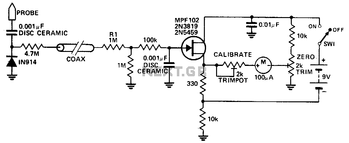
This circuit measures RF voltages exceeding 200 MHz and reaching up to approximately 5 V. The diode must be installed in a remote probe, positioned near the probe tip. The sensitivity is exceptional, allowing for the measurement of voltages...
This circuit generates a readout for a digital tachometer. IC9 functions as a 3-digit LED display driver, counter, and latch. IC8 operates the common cathode LEDs, which are activated by transistors Q1, Q2, and Q3. Refer to page 268,...