
Electronic Watchdog

The electronic watchdog circuit is designed to enhance security by simulating the presence of a dog. It typically consists of several key components, including a motion sensor, a sound module, a microcontroller, and a power supply.
The motion sensor, often an infrared (IR) or ultrasonic type, detects movement within the specified 10-meter radius. Upon detecting motion, it sends a signal to the microcontroller, which processes the input and activates the sound module. The sound module is programmed to produce a barking sound that mimics a real dog, enhancing the deterrent effect.
The microcontroller plays a crucial role in managing the operation of the circuit. It is programmed to initiate the barking sequence for a duration of 10 seconds. If the motion sensor continues to detect movement after this time, the microcontroller can be configured to either repeat the barking sound or enter a standby mode, effectively reducing power consumption when no further activity is detected.
Power supply options for the circuit may include batteries or a direct connection to an AC source, depending on the intended application and installation location. The circuit can be housed in a weatherproof enclosure for outdoor use, ensuring durability and reliability in various environmental conditions.
Overall, the electronic watchdog circuit combines advanced sensing technology with realistic sound output to create an effective security solution that can help deter unauthorized entry into a premises. As shown for the electronic watchdog circuit. It has the ability of ordinary dog guard the house. Whenever someone enters the door 10 meters monitored area, it will send out a realistic barking. Such calls can be maintained for 10 seconds, if the person does not leave, the electronic watchdog would have been called down.
Related Circuits
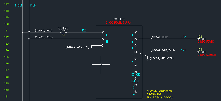
The power supply unit (PSU) in question does not appear to be exceptionally large. Eagle software should be capable of managing these dimensions. The focus was more on finding an alternative that may already include the necessary components and...
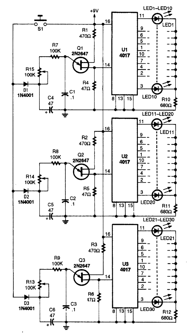
The one-arm bandit circuit consists of three clock circuits and three counter/readout circuits. A single roll switch, S1, activates all three clocks simultaneously. When S1 is closed, capacitors C4, C5, and C6 charge through diodes D31, D32, and D33...
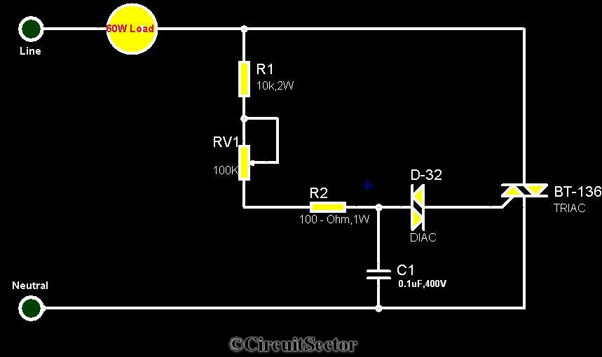
The circuit diagram presented is a triac-diac electronic fan regulator designed to reduce power consumption of electric fans, even at low speeds. Traditional resistor-inductor fan regulators tend to generate excess heat, wasting energy when the fan operates at lower...

The goal of Advanced Digital Electronics courses is to connect basic logic gates (combinational circuits) with technical subjects related to binary counter topologies (both Asynchronous and Synchronous), shift registers, memory, and Digital Signal Processors (DSP), which are categorized as...

This electronic circuit, based on the CD4017 and logic gates, activates a relay when four keys are pressed in the correct sequence, returning to the initial state afterward. The circuit utilizes the CD4017 decade counter, which is designed to count...
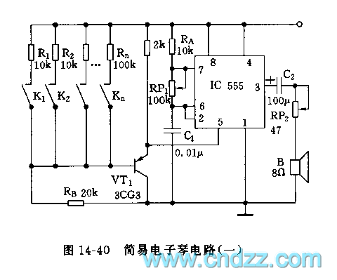
The controllable multivibrator, as illustrated in figure 14-40, consists of a 555 timer along with resistors RA, RP1, and capacitor C1. The oscillation frequency is influenced by the control voltage applied to pin 5. This control voltage is determined...
Warning: include(partials/cookie-banner.php): Failed to open stream: Permission denied in /var/www/html/nextgr/view-circuit.php on line 713
Warning: include(): Failed opening 'partials/cookie-banner.php' for inclusion (include_path='.:/usr/share/php') in /var/www/html/nextgr/view-circuit.php on line 713