
Water Alarm Circuit
To create an effective water leak detection and alert system, a schematic can be designed utilizing several electronic components. The system typically includes a water sensor, a microcontroller, a buzzer or alarm, and a power supply.
The water sensor, often a conductive type, is placed in areas prone to leaks, such as near water heaters, under sinks, or around aquariums. This sensor detects the presence of water by measuring conductivity between its probes. When water is detected, the sensor sends a signal to the microcontroller.
The microcontroller, which can be an Arduino or a similar programmable unit, interprets the signal from the water sensor. Upon receiving a signal indicating the presence of water, the microcontroller activates an alarm system. This alarm can be a simple buzzer or a more sophisticated notification system that sends alerts to a smartphone or central home automation system.
The power supply is typically a low-voltage DC source, which can be derived from a wall adapter or batteries, ensuring that the system remains operational even during power outages.
The schematic layout will include the connections between the water sensor, the microcontroller, and the alarm system. The water sensor will be connected to one of the digital input pins on the microcontroller. The buzzer or alarm will be connected to a digital output pin, allowing the microcontroller to trigger it when necessary. Additionally, it may include a reset button to silence the alarm after the water issue has been addressed.
This system provides a proactive approach to water leak management, allowing homeowners to mitigate potential damage by receiving timely alerts before a leak escalates into a more significant problem.Have you ever seen the stairs to one of the upper stories in your house turn into a waterfall? Or maybe you ve come home to find your aquarium fish trying to swim across the carpet? For your sake, we hope not, because the consequences are usually fairly dramatic. With a handful of electronic components, you can at least ensure that you will be warned before you have to put on your waders. It s better to prevent water problems than to have to correct them. But no how many precautions you take, an occasional leak can still happen.. 🔗 External reference
Related Circuits
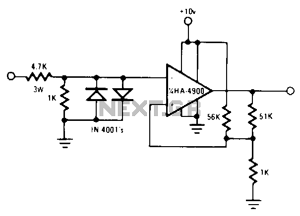
Utilize a pair of Maxim's 5V-powered MAX231 RS-232C transmitters as drivers to achieve a dual-color LED. These transmitters necessitate only a single-ended, 5-V input to internally generate ±10 V. Their outputs are designed to be short-circuit-proof and can provide...
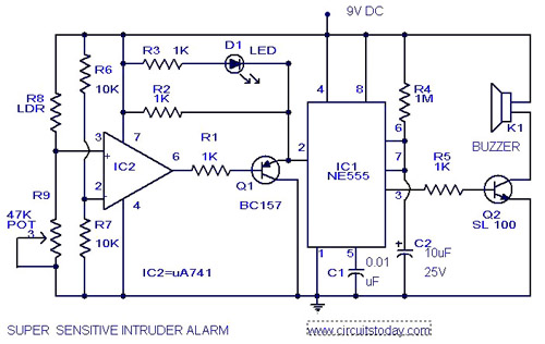
The circuit diagram represents an ultra-sensitive intruder alarm. A shadow from an intruder passing nearby is sufficient to trigger the alarm. The operational amplifier IC2 (uA 741) is configured as a sensitive comparator, with its set point determined by...

This light-dependent sensor utilizes light-dependent resistors (LDRs) to detect the presence or absence of light. The alarm remains inactive as long as the light source illuminating the LDRs is constant. However, if the light is interrupted, the alarm is activated. The...
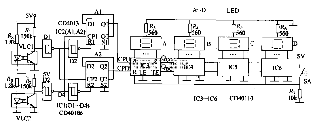
This document describes an electronic winding machine with manual, electric, and semi-automatic features. The specific example highlighted includes an electronic counting function that assists users in managing motor windings. The circuit design consists of various components as illustrated in...
This page provides information on circuits that can trigger stroboscopes from external circuits. The circuits are designed to be integrated into stroboscope systems, allowing them to be activated using an external trigger pulse. The standard trigger pulse utilized in...
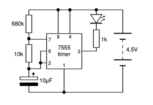
The 7555 timer IC used is a low power version of the standard 555 timer. A super bright red LED is utilized because it provides a bright flash with low current. The 7555 timer IC is a versatile low-power component...
Warning: include(partials/cookie-banner.php): Failed to open stream: Permission denied in /var/www/html/nextgr/view-circuit.php on line 713
Warning: include(): Failed opening 'partials/cookie-banner.php' for inclusion (include_path='.:/usr/share/php') in /var/www/html/nextgr/view-circuit.php on line 713