
water level indicator using 7 segment display

The water level indicator circuit utilizes a straightforward design to monitor and display the water level in a tank. The primary components include a 7-segment display, which serves as the visual output for the user, and two integrated circuits (ICs) that handle the logic operations necessary for interpreting the sensor signals.
The 7408 quad two-input AND gates IC is crucial for this circuit, as it processes the signals from the level sensors. Each sensor corresponds to a specific water level: the low sensor triggers when the water level falls below a predetermined threshold, the half sensor activates when the tank reaches the halfway point, and the high sensor signals when the tank is full. The overflow sensor serves as an additional safety feature, ensuring that if the water level exceeds the tank's capacity, an alert is displayed.
The 7404 hex inverter IC complements the logic operations by inverting the signals received from the sensors. This inversion is essential for ensuring that the correct levels are indicated on the 7-segment display. For instance, when the low sensor is activated, the AND gates process this input and send a signal to the display to show 'L'. Similarly, the circuit logic ensures that only one indicator is active at any given time, preventing confusion in the displayed water level.
The five level sensors are typically arranged in a vertical configuration within the tank, allowing them to detect varying water levels effectively. The common ground sensor establishes a reference point for the other sensors, ensuring accurate readings. The overall design is efficient and cost-effective, making it suitable for various applications, including home water tanks, aquariums, and industrial water management systems.Using this schematic electronic project can be designed a very simple water level indicator electronic circuit that uses a 7-segment display to indicate the water level (low, half and full)in the tank. This water level indicator electronic circuit shows the water level by displaying L, H and F for low, half and full, respectively.
This water level indicator electronic circuit is based on the 7408 quad two inputs and gates IC (that contains four input independent gates) and a 7404 hex inverting gates IC. The circuit uses five level sensors to sense the different water levels ( one for common GND, one for low, one for high one for half and one for overflow ).
🔗 External reference
Related Circuits
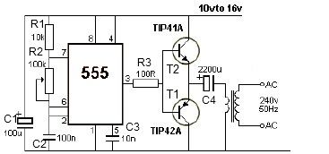
12V power inverter circuit utilizing a 555 timer for an electronic project. The 12V power inverter circuit is designed to convert a DC voltage of 12 volts into an AC voltage suitable for powering small electronic devices. The core component...
The quartz crystal oscillator circuit is highly advantageous in terms of frequency stability. Even the Voltage-Controlled Crystal Oscillator (VCXO) circuit, which allows for significant frequency changes, typically experiences only about a 1% variation. However, the linear range of control...
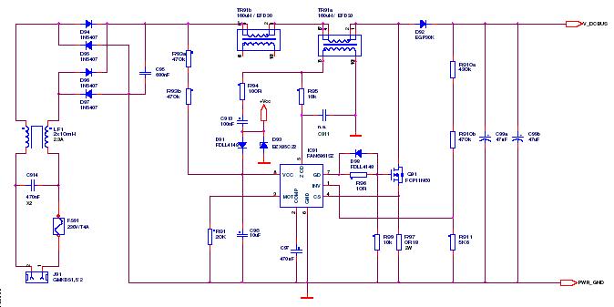
This article outlines a proposed solution for a 200 W power supply utilizing the FSFR2100 Fairchild Power Switch (FPS). The input voltage range is 90 to 265 VRMS, and it features six outputs. The 200 W power supply circuit based...
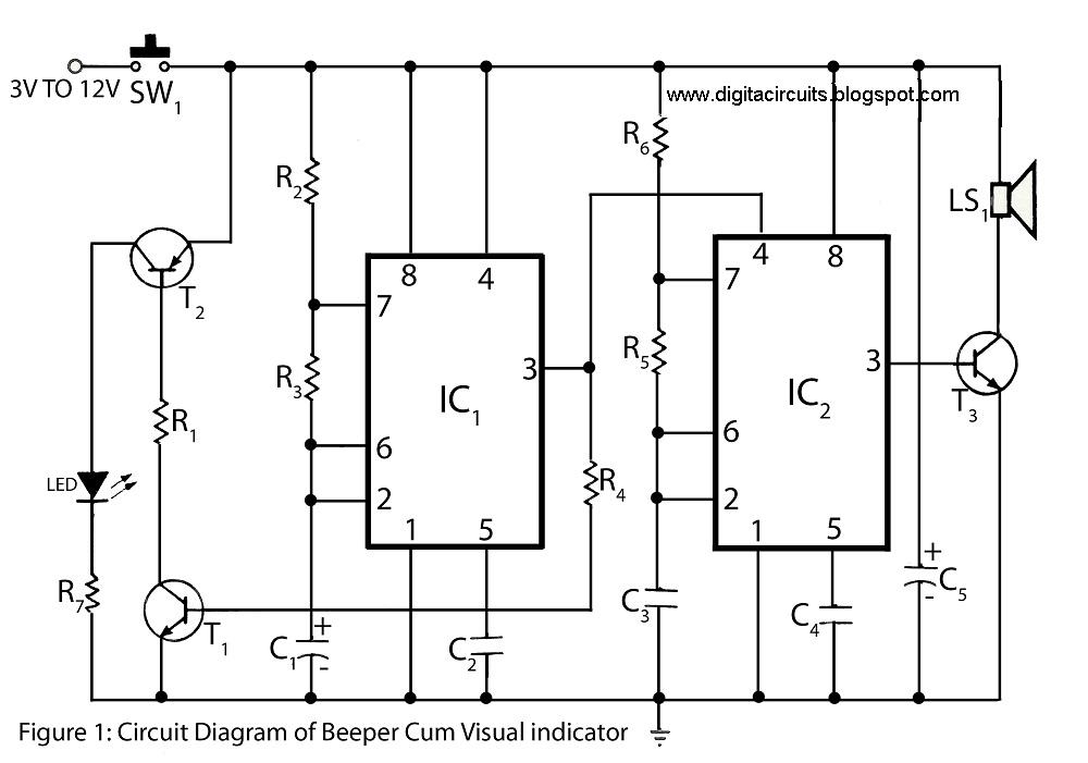
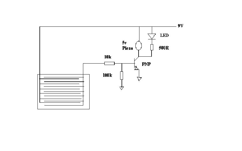
This circuit of a beeper and visual indicator is constructed using two timer integrated circuits (ICs) configured in an astable multivibrator mode. The frequency produced by IC1 is regulated by capacitor C1. The output from pin 3 of IC1...
This project outlines a simple water detector circuit. The components required for this project include the following: 1. One IC 555 timer, and 2. A small-sized general-purpose relay. The water detector circuit utilizes the IC 555 timer configured in a...
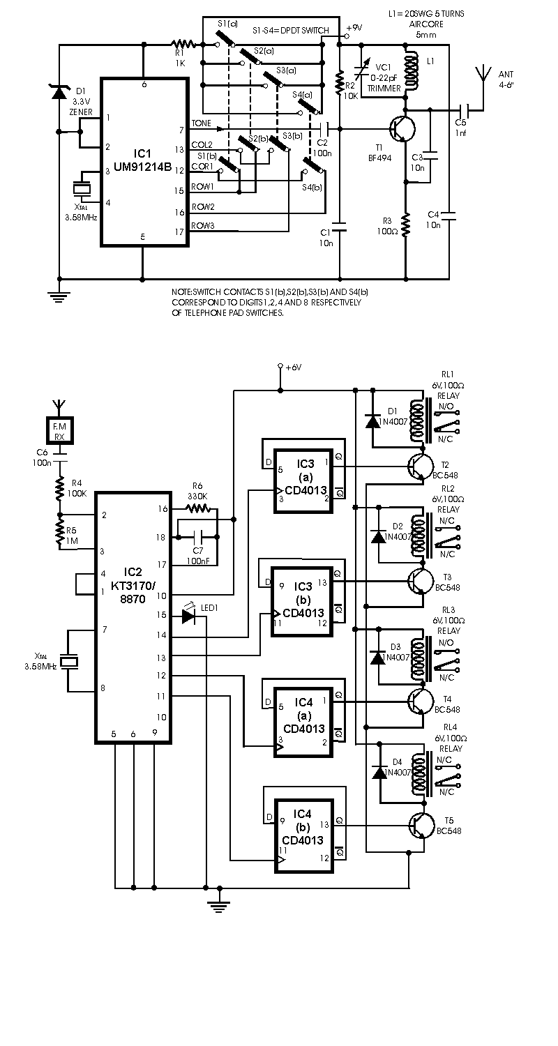
Here is a circuit of a remote control unit which makes use of the radio frequency signals to control various electrical appliances. This remote control unit has 4 channels which can be easily extended to 12. This circuit differs...