
Build a Beeper visual indicator

The circuit operates as a dual-function indicator, providing both auditory and visual signals. The astable multivibrator configuration allows for continuous oscillation, generating a square wave output. Timer IC1 is responsible for generating a frequency that determines the rate of blinking for the visual indicator and the beeping sound from the beeper.
Capacitor C1 plays a crucial role in setting the oscillation frequency of IC1. By selecting the appropriate capacitance value, the timing characteristics can be adjusted to achieve the desired blinking rate for the visual indicator. The output from pin 3 of IC1, which produces the square wave signal, is routed to the input of IC2. This second timer IC can be used to further amplify the signal or to generate a different frequency if desired.
The voltage amplifier transistor T1 is employed to amplify the signal from IC1, allowing for better control over the subsequent components. Resistor R4 serves to limit the base current to T1, ensuring that it operates within safe limits. The amplified output can then be used to drive additional loads or indicators.
The flashing light is connected to the collector of switching transistor T2, which acts as a switch to control the light's operation. When T2 is activated by the output of T1, the light will flash in synchronization with the beeping sound, providing a visual cue in addition to the auditory signal. Resistor R7 ensures that the circuit is properly grounded, completing the circuit for the flashing light.
Overall, this beeper and visual indicator circuit is versatile and can be adapted for various applications, such as alarms, timers, or notification systems, where both sound and light signals are beneficial for alerting users.This entire circuit of beeper cum visual indicator is build and fabricated around two timer ICs and is configured in an astable multivibrator mode. The frequency generated by IC1 is controlled by capacitor C1. The output from pin 3 of IC1 is given to input pin 4 of IC2 and base of voltage amplifier transistor T1 through resistor R4.
Flashing light is connected to collector of switching transistor T2 and grounded through resistor R7. 🔗 External reference
Related Circuits
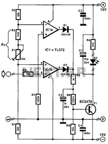
Two operational amplifiers are utilized as comparators to signal an excessive magnitude of an audio frequency (AF) signal, regardless of whether the signal is positive, negative, or asymmetrical. A reference voltage is established for both operational amplifiers using a...

24V DC is a widely used voltage in industrial environments. The circuit illustrated below is designed to accept four different 24V DC alarm input signals, which are utilized to activate a single low-power beeper. The beeper is a magnetic...
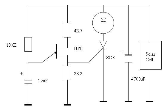
A discussion on the application of the PIC16F84 microcontroller for control and robotics, as well as instructions for programming the PIC16F84/A microcontroller. The solar engine is frequently utilized as an onboard power source for BEAM-type robots, sometimes referred to...
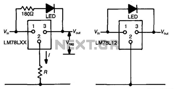
The three-terminal regulator device (LM78LXX) provides an output voltage (Vout) equal to the input voltage (Vm) until the input voltage exceeds the output voltage by 1.5 to 2 volts. A regulated voltage (Vreg) is achieved at this point, with...
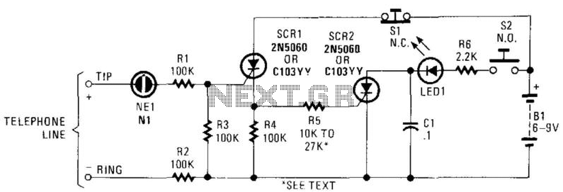
In this circuit, the ringing voltage on a telephone line causes NE-1 to break over, triggering SCR1, which in turn triggers SCR2. If a call has been received, depressing S2 will cause LED1 to light. Depressing S1 resets the...
This circuit features an intermittent siren output and automatic reset. It can be operated manually using a key switch or a hidden switch, and it can also be wired to activate automatically when the ignition is turned off. By...