
wein bridge oscillator using jfet
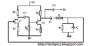
The Wien bridge oscillator is a well-established circuit configuration used for generating sine waves. It consists of a feedback network formed by a balanced Wien bridge, which is composed of resistors and capacitors arranged in a specific manner to determine the frequency of oscillation. The two-stage common source amplifier is critical in achieving the required phase shift and gain necessary for sustained oscillation.
In the Wien bridge configuration, the bridge consists of two resistors and two capacitors. The resistive arms of the bridge are typically equal, which ensures that the bridge is balanced at the desired frequency. The frequency of oscillation is determined by the values of these components, specifically the resistors and capacitors used in the bridge.
The two-stage common source amplifier provides the necessary phase shift and amplification. The first stage amplifies the signal, while the second stage further amplifies the output. The design must ensure that the total phase shift around the loop is 360 degrees, which is crucial for oscillation. The gain of the amplifier stages must be carefully calculated to ensure that the loop gain is unity at the resonant frequency of the bridge.
To maintain oscillation, the gain of the amplifier should be slightly greater than 3 to account for any losses in the circuit, such as those arising from non-ideal components or parasitic elements. This slight increase in gain ensures that the oscillations can start and sustain themselves.
The overall gain of the two-stage amplifier is the product of the gains of the individual stages. If each stage is designed to provide a gain of approximately 1.5, the total gain would be around 2.25, which is insufficient. Therefore, each stage must be optimized to achieve a total gain of at least 3, with considerations for additional compensation for losses.
In summary, the Wien bridge oscillator is a sophisticated circuit that requires precise component selection and gain calculations to function effectively. Its ability to produce stable sine wave oscillations makes it valuable in various applications, including signal generation and testing in electronic circuits.The wein bridge osillator employs as balanced wein bridge as the feedback network. Two stage common source amplifier provide 360 degree phase shift to the signal. The attenuation of the bridge is calculated to be 1/3 at resonant frequency. There for the amplifirer stage should provide a gain of 3 to. make loop gain unity. Gain preferred to slightl y greater than 3 to compensate for the losses occuring in the circuit. Since gain of two stage amplifier is the product of individual stages, over all gain may become very high. 🔗 External reference
Related Circuits
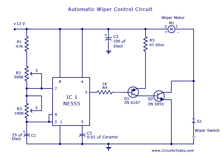
A circuit for car windshield/wiper motor speed control built using an NE 555 IC. This enables intermittent windshield wiper control, which changes the sweep rate to 10 seconds. The circuit utilizes the NE 555 timer IC configured in astable mode...
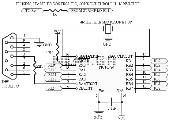
This project uses only a few of the instructions that come with PicBasic, but serves to show how easy PicBasic really is. It also shows how PicBasic strongly resembles programming the BASIC Stamp. Here we are using the serin...
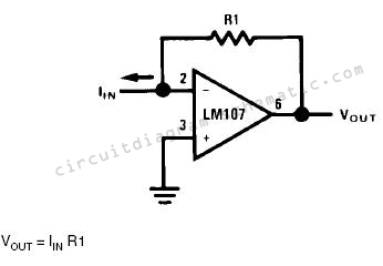
Converting current into voltage is undesirable for two reasons: first, an impedance is inserted into the measuring line, causing an error; second, amplifier offset voltage is also amplified, leading to a subsequent loss of accuracy. The use of a...
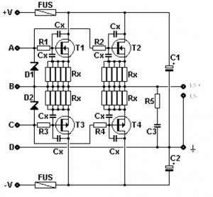
Amplifier circuit featuring a MOSFET output stage, serving as an alternative to the output stage that utilizes bipolar transistors. Advantages of the MOSFET amplifier include ease of operation, the ability to handle hundreds of watts with straightforward parallel configurations,...
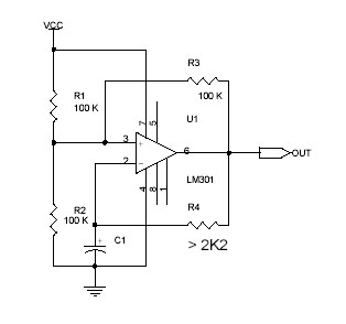
This circuit utilizes the Op-Amp LM301 to generate a simple square wave. The LM301 operates with a power supply range of 3 V to 36 V and can handle a maximum frequency of 325 kHz. The oscillation frequency is...
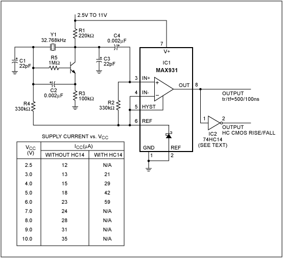
Design a 32kHz wide supply range oscillator with a low-power comparator, a reference, and crystal oscillator. The circuit design involves creating a 32kHz oscillator that operates efficiently across a wide supply voltage range. The core components include a low-power comparator,...
Warning: include(partials/cookie-banner.php): Failed to open stream: Permission denied in /var/www/html/nextgr/view-circuit.php on line 713
Warning: include(): Failed opening 'partials/cookie-banner.php' for inclusion (include_path='.:/usr/share/php') in /var/www/html/nextgr/view-circuit.php on line 713