
Which only uses the 5V power supply connection circuit
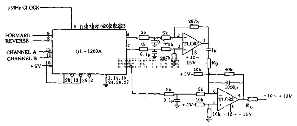
The circuit operates by converting the error signal into a PWM output, which modulates the width of the pulses to control the power delivered to the load—in this case, a DC motor. The input error signal is derived from the differential position error, calculated based on the system's position feedback from the sensors located at 6 and 7 feet. This feedback is essential for maintaining the desired position of the motor.
The PWM signal is generated by comparing the error signal against a reference signal within a comparator circuit. The output of this comparator drives a power amplifier, which is responsible for supplying the necessary current to the motor. The operational amplifiers in the circuit play a critical role in signal conditioning and ensuring that the error signals are appropriately scaled and filtered. The first operational amplifier processes the error signal and applies damping to reduce oscillations and improve stability.
The gain and damping of the system are set using resistors RD and R, which form part of the feedback network in the operational amplifiers. By adjusting these resistors, the performance of the motor control system can be fine-tuned to achieve desired response characteristics, such as settling time and overshoot. This adjustment is crucial for applications requiring precise control over the motor's position and speed.
Overall, this circuit design emphasizes the importance of feedback control in motor applications, utilizing PWM for efficient power management and operational amplifiers for effective signal processing, ensuring robust performance in dynamic environments.Error processing segment is converted to a pulse width modulated (PWM) signal output from 3 feet (MC signal). Also calculate the differential position error, which represents t he small velocity, from 6 and 7 feet elected as a system with damping. A speed proportional to their positive and the other negative is proportional to the speed. Two signal into an analog channel in an external operational amplifier damping in number. With another damping operational amplifier and the position error signal as a synthesis may be an analog signal for controlling the power amplifier final stage, driving a DC motor. (See Fig. 13-17). Gain and damping by two resistors RD and R. systems to adjust, Tsui excellent performance of the system.
Related Circuits
This infrared alarm barrier is designed to detect individuals passing through doorways, corridors, and small gates. The transmitter emits an invisible beam of infrared light. When this beam is interrupted by a person, a buzzer connected to the receiver...
The application that we propose is a simple filter that limits the acoustic region (20-20000Hz) to the region 20-100Hz. With the manufacture proposed, an active filter can be created to drive a loudspeaker for very low frequencies. This allows...
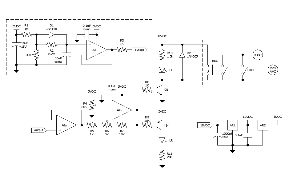
Approximately ten days ago, an all-linear automatic night light circuit was installed to control the lights in the living room. The circuit comprises three operational amplifiers (op-amps): two configured as voltage followers and one as a comparator. As depicted...
The circuit described can connect two telephones in parallel and function as a two-line intercom. Typically, a single telephone is connected to a telephone line. When another telephone is needed at a distance, a parallel line is utilized for...
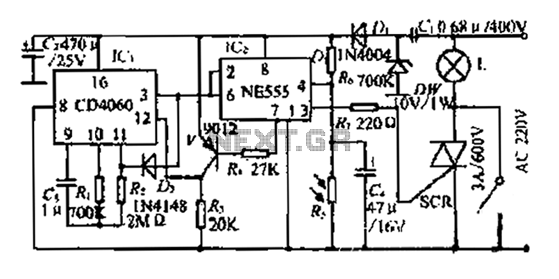
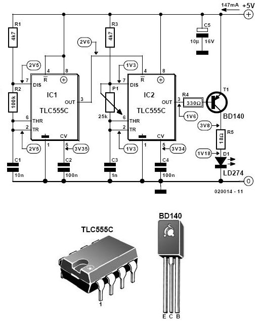
A photosensitive daytime electricity circuit utilizes a very small positive voltage. It features a 555 timer IC with four pins, including a reset pin that operates at low voltage. The circuit includes a bidirectional thyristor (iSCR) that controls lighting,...

This design circuit is for audio graphic equalizers, which are commonly found as commercial products, yet published circuits for them are quite rare. The circuit features a simple design that requires an operational amplifier (op-amp) to amplify the input...