
Why are 555 IC pin diagrams so random
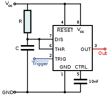
The 555 timer IC is a versatile device widely used in various electronic applications, including timing, pulse generation, and oscillation. It generally comes in an 8-pin dual in-line package (DIP) format, where the pin configuration is standardized across most manufacturers. The standard pinout includes pins for power supply, ground, trigger, threshold, discharge, control voltage, reset, and output.
Despite the standardization, variations can exist between manufacturers, particularly in the electrical characteristics and maximum ratings of the components. It is essential to refer to the specific datasheet of the manufacturer to confirm the exact pin configuration and electrical specifications, as this can impact the circuit's performance.
When designing circuits with the 555 timer, it is advisable to maintain a clear and consistent schematic that reflects the actual pin configuration used in the circuit. If custom routing is necessary to accommodate different pin arrangements, it is crucial to document these changes meticulously to avoid confusion during assembly or troubleshooting. Additionally, using a breadboard for prototyping can help visualize the connections before finalizing the PCB layout, ensuring that the intended functionality is achieved without ambiguity.
In summary, while the 555 timer chips are largely interchangeable, attention must be paid to the specific pin configurations and characteristics of the selected component to ensure proper functionality in any given application.Can I assume that most of the 555 chips from different manufacturers are interchangable (same pin configuration), however the programs/diagrams have pins that way just to look simpler I can always route my own weird ways on the actual chip to match the configuration in the schematics, however that is confusing due to it changing each time. 🔗 External reference
Related Circuits
Prototype board for 40-pin Atmel ATMega microcontrollers featuring a power supply circuit, an 8MHz crystal oscillator circuit, an RS232 port, a reset IC, a status LED, and a 10-pin STK ICSP port. Constructed from FR-4 material, 1.5 mm thick. The described...
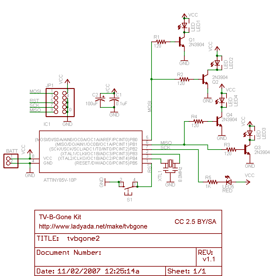
Why use one resistor and one transistor for each LED instead of connecting the LEDs in series and controlling them with a single transistor? This approach is controlled by an Arduino pin through a single resistor. While there is...
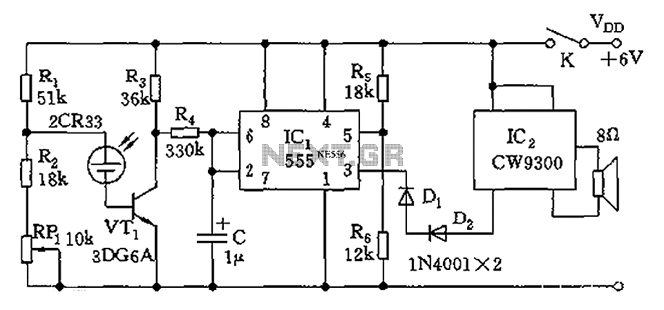
The circuit utilizes photoelectric sensors and a 555 timer to respond to music prompts. The illumination sensor components consist of photovoltaic cells (2CR33). When the light level drops below the optimal learning illumination of 100 lux, the 2CR33 exhibits...

This circuit illustrates an automatic room light circuit diagram. It features a small memory component that allows it to automatically switch on and off. The automatic room light circuit is designed to enhance energy efficiency and convenience by utilizing a...
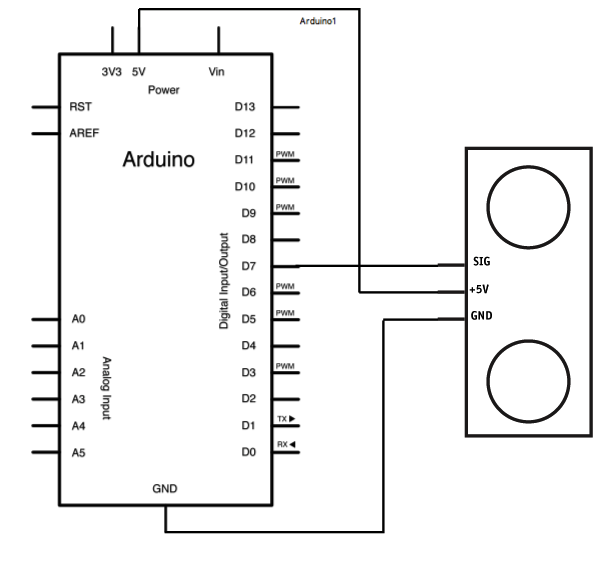
The Ping is an ultrasonic range finder from Parallax. It detects the distance of the closest object in front of the sensor (from 2 cm up to 3 meters). It operates by emitting a burst of ultrasound and listening...

555 precision temperature sensor with temperature frequency converting circuit diagram consisting of: The 555 precision temperature sensor operates by converting temperature variations into frequency signals. This circuit typically utilizes a 555 timer IC configured in astable mode to generate...
Warning: include(partials/cookie-banner.php): Failed to open stream: Permission denied in /var/www/html/nextgr/view-circuit.php on line 713
Warning: include(): Failed opening 'partials/cookie-banner.php' for inclusion (include_path='.:/usr/share/php') in /var/www/html/nextgr/view-circuit.php on line 713