
Wien-Bridge Oscillator Using HA2541 Op-Amp
The Wien-Bridge oscillator is a type of electronic oscillator that produces sine waves. It employs a bridge circuit consisting of resistors and capacitors to determine the oscillation frequency. The operational amplifier HA2541 serves as the core amplification element, ensuring that the output sine wave maintains its quality and stability.
In this configuration, the resistors R1 and R2, along with capacitors C1 and C2, form the frequency-determining network. The values of these components can be selected to set the desired output frequency, while ensuring that the total gain of the amplifier exceeds three. This is crucial for sustained oscillation, as a gain of exactly three would result in a neutral balance, preventing oscillation from occurring.
The inclusion of resistors R8 and R9 allows for fine-tuning of the gain, compensating for any losses that may occur in the circuit. The diodes D1 and D2 are employed for amplitude stabilization; they limit the output voltage to prevent distortion of the sine wave at higher amplitudes, thus preserving the integrity of the signal.
The circuit's design emphasizes frequency stability, which is achieved through the regenerative feedback mechanism. The feedback network, formed by R2/C2 and R1/C1, provides the necessary phase shift and gain to sustain oscillation. This is particularly important in high-frequency applications, where even minor variations can significantly impact performance.
In summary, the Wien-Bridge oscillator utilizing the HA2541 is a sophisticated circuit capable of generating precise sine waves at high frequencies, with careful consideration given to gain, feedback, and amplitude stabilization.A Wien-Bridge oscillator circuit can be built from HA2541 and some basic components. This circuit can generate good-quality sine wave of 40 MHz with an upper limit of 50 MHz. The R3 through R7 and D2 and D1 provide the diode limiting for this circuit. Here is the schematic diagram of this circuit: For frequency stability, this circuit need a reg enerative feedback. The feedback network is formed by R2/C2 and R1/C1. To obtain the oscillation, the gain required is three but practically we need gain over three. So R9 and R8 is added to this circuit to provide gain over three times. 🔗 External reference
Related Circuits
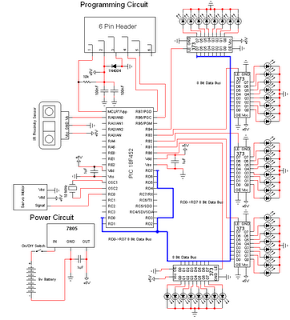
The personal radar system utilizes the PIC microcontroller PIC18F452 as a hobby project. The attached circuit diagram of the radar may appear simple; however, careful analysis of the PIC18F452 radar circuit is necessary to prevent damage. This personal radar...
Create a basic RF oscillator. The circuit is very simple, so complex calculations will be omitted, and component selection will be simplified using calculators. For this example, the target frequency is 7 MHz. The circuit includes a transistor (TR1)...
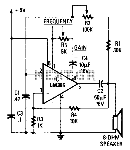
The circuit's frequency of oscillation is given by the formula: f = 2.8 / [C1 x (R1 + R2)]. By adjusting the potentiometer R2, the output frequency can be varied from 60 Hz to 20 kHz. A portion of...
The square wave oscillator does not necessarily need to be a 555 timer; it can also be implemented using a ring oscillator with inverters. However, when utilizing 4000 series CMOS logic, the negative output voltage generated may have limited...
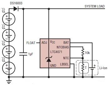
A simple solar-powered battery charger circuit can be designed using the LTC4071 Li-Ion/Polymer Shunt Battery Charger System with Low Battery Disconnect. When VCC reaches the programmed float voltage (4.1V with ADJ floating), the LTC4071 shunts excess current not used...
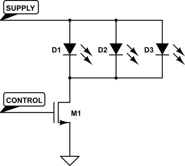
A Common Cathode LED strip is being utilized instead of a Common Anode variant, leading to the development of a modified circuit. The experience with FETs was limited, resulting in challenges as a minimum voltage equal to Vcc is...