
Wien oscillator
To construct a sine wave generator using a Wien bridge oscillator configuration with the TL082 operational amplifier, the following components are essential: two resistors (R1 and R2), two capacitors (C1 and C2), and a variable resistor (Rf) to form the feedback network. The values of R1 and R2 should be equal to ensure the feedback loop maintains the desired frequency of oscillation, while C1 and C2 should also match in value to establish the correct phase shift for sine wave generation.
The circuit operates by balancing the gain of the op-amp with the feedback resistance Rf. The Wien bridge oscillator requires a gain of 3 to sustain oscillation. Therefore, Rf must be adjusted carefully to achieve this gain without causing distortion. A typical configuration would use R1 and R2 values in the range of 10kΩ, paired with capacitors C1 and C2 of 10nF, resulting in a frequency of approximately 1.59 kHz.
The use of a 1kΩ linear potentiometer as Rf allows for fine-tuning of the feedback gain. However, if oscillation ceases at a low resistance setting, it indicates that the gain is insufficient, necessitating a smaller potentiometer in series to allow for a more precise adjustment. The filament bulb's non-linear resistance characteristics can influence the circuit's stability, so ensuring that it operates within a current range that allows for visible light emission is critical.
In conclusion, careful selection of component values and adjustments of the feedback resistor are vital in achieving a stable and accurate sine wave output. The use of matched components and fine-tuning the feedback loop will help mitigate distortion and enhance the performance of the sine wave generator.Build a sine wave generator. I use this schematic:. The op-amp I have used is the TL082 and the power supply of 9V. However, I do get a nasty sound, indicating that I am not getting a sine wave but rather a distorted waveform. Any idea why this is happening Do you know any list of components for the wien oscillator that can generate accurate sine waves Note that the explanation is
that the self heating causes the resistance of the bulb to stabilise at around Rf/2. You need to choose Rf such that Rf/2 is an achievable resistance for the filament at a reasonable (small) current. I am trying to build a sine wave generator. I use this schematic:. The op-amp I have used is the TL082 and the power supply of 9V. However, I do get a nasty sound, indicating that I am not getting a sine wave but rather a distorted waveform.
Any idea why this is happening Do you know any list of components for the wien oscillator that can generate accurate sine waves Thanks Dave and Steve! I bought a linear 1k potentiometer to use as Rf, but I`m still not getting a sine (I keep getting the nasty sound).
The bulb I am using is 12V 65mA. Is the small current in the fillament enough to cause the bulb to emit visible light At what point in the travel of the 1k trimpot does oscillation cease If it is right up against the end stop (near zero ohms) then you should replace the trimpot with one of a much smaller resistance. The correct adjustment of the 1k pot is somewhere between the point where there is no sustained oscillation and where the output is a square wave.
You see one of these extremes, do you see the other It may even help to place a smaller value trimpot in series with a larger one so you have expanded control around the critical point. The critical point may vary slightly between ranges. The latitude in adjustment (caused by the non-linear nature of the bulb) should allow you to find a setting which works for all ranges.
🔗 External reference
Related Circuits
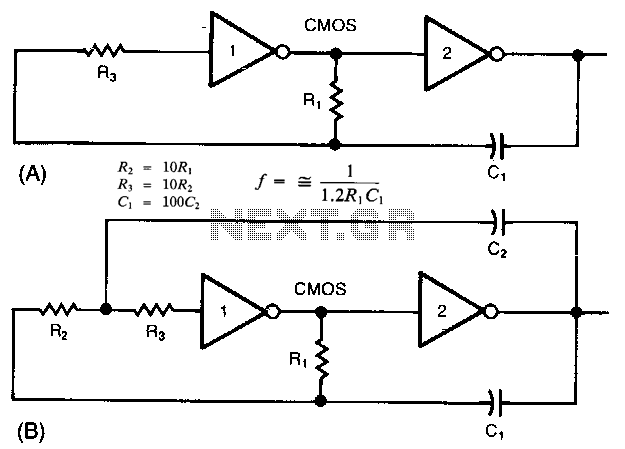
The common clock oscillator illustrated in Fig. 68-19A has two minor issues: it may not oscillate if the transition regions of its two gates differ. If it does oscillate, it might occasionally operate at a slightly lower frequency than...
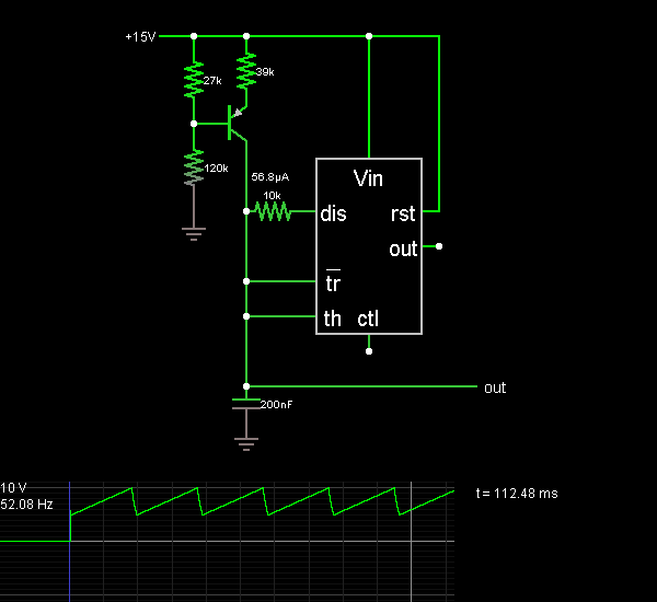
This document presents the 555 Sawtooth Oscillator circuit diagram along with a detailed explanation of its operational principles. An electronic circuit simulator is available to assist in designing the 555 Sawtooth Oscillator circuit and simulating it online for enhanced...
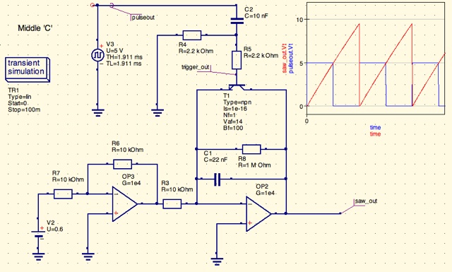
A design for a digitally controlled analog oscillator is being developed. The control voltage is generated by a microcontroller (Arduino) and is utilized through two operational amplifiers, along with a resistor and capacitor network that forms an integrator circuit....
This circuit is a crystal oscillator that operates at a frequency of 3.5 MHz. The crystal oscillator circuit utilizes a quartz crystal resonator to generate a stable frequency output. The primary components typically include the crystal, an amplifier (often a...

A CD4093 chip and several components form a siren oscillator that drives power MOSFET Tl. A speaker is directly powered by this device. The siren is activated by a logic high signal applied to the ENABLE input. The circuit comprises...
Free energy motors and generators are available for purchase, featuring plans for overunity devices. These devices resemble oscillators used in Joule thief circuits, although there may be some errors present in the designs. However, the concept remains clear. Free energy...